


In the realm of business analysis and process management, clear communication is paramount. Business Process Model and Notation (BPMN) serves as the global standard for visualizing business processes, bridging the gap between business strategy and technical implementation. At the heart of every effective BPMN diagram lies a standardized set of building blocks. By mastering these fundamental elements, Business Analysts and process modelers can create diagrams that are not only visually intuitive but also technically accurate. This guide provides a comprehensive breakdown of the core BPMN flow objects, their specific variations, and the underlying philosophy that makes this notation so universally effective.
The Foundation: Sequence Flow
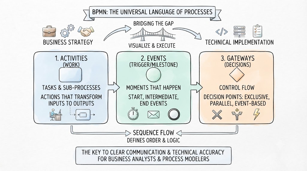
Before diving into the specific nodes of a process, it is essential to understand how they connect. Sequence Flow is the fundamental connector used in BPMN models. Represented by solid lines with arrowheads, Sequence Flow defines the underlying structure and behavioral paths of a process. It dictates the exact order in which Activities, Events, and Gateways are executed, ensuring the logical progression of the workflow from start to finish.
1. Activities: The Work of the Process
Activities represent the actual work performed within a process. Visually, they are depicted as rounded-corner rectangles. They are the heavy lifters of your BPMN model, detailing the actions that transform inputs into outputs.
Activities are broadly categorized into two core types:
- Tasks: These are atomic, indivisible units of work. They represent the lowest level of detail in a process model.
- Sub-Processes: These are compound activities that encapsulate a larger, more complex piece of work. They can be broken down further into their own detailed sub-process models.
Note for Business Analysts: When modeling at the task level, the primary core Task type utilized is the None Task (a standard task with no specific triggering or execution modifiers), which serves as the baseline for general work execution.
2. Events: The Triggers and Milestones
Events represent something that “happens” during the lifecycle of a process. Unlike activities, events do not represent work; rather, they represent moments in time, triggers, or outcomes. Visually, all events are represented by circles, but their border thickness indicates their specific role in the process flow.
Events are strictly categorized by their position in the workflow:
Start Events
- Visual: Represented by a thin line circle.
- Function: They show exactly where a process begins and act as the initial trigger for the workflow.
- Core Types:
- None: A standard start with no specific trigger.
- Timer: The process starts at a specific time or after a duration.
- Message: The process is triggered by the arrival of a message.
- Signal: The process is triggered by a broadcast signal.
Intermediate Events
- Visual: Represented by a double thin line circle.
- Function: These occur strictly between a Start and an End event. They often represent delays, waiting periods, or interruptions that alter the flow.
- Core Types:
- None: A standard intermediate catch or throw.
- Timer: Introduces a delay or wait time in the process.
- Message: Catches or throws a message during the process execution.
- Signal: Catches or throws a signal during execution.
End Events
- Visual: Represented by a thick line circle.
- Function: They mark the definitive conclusion of a process path. Once an end event is reached, the specific path of execution is terminated.
- Core Types:
- None: A standard, plain completion of the process.
- Message: The process ends by sending a final message.
- Signal: The process ends by broadcasting a final signal.
3. Gateways: The Decision Makers
Gateways are the control points of a BPMN model. Visually depicted as diamonds, they are used to control the divergence and convergence of Sequence Flow. They dictate how the process path splits into multiple directions or merges back together.
The core set of Gateways includes:
- Exclusive Gateway (XOR): Used for decision-making where only one path can be taken based on a condition. It acts as a strict “either/or” fork in the road.
- Parallel Gateway (AND): Used to create concurrent paths. It splits the flow so that multiple paths are executed simultaneously, or merges multiple concurrent paths back into a single flow.
- Event-Based Gateway: Used for branching based on which event occurs first. Instead of evaluating data conditions, the process waits, and the path taken is determined by whichever intermediate event (like a timer or a message) is triggered first.
The Design Philosophy of Core BPMN
The specific core elements outlined above are not arbitrary; they are the result of a deliberate design philosophy. The Business Process Model and Notation standard is designed to be simple and readable. By restricting the core vocabulary to these essential Activities, Events, and Gateways, BPMN provides just enough functionality to model the vast majority of business process behaviors without overwhelming the reader with unnecessary complexity. This balance ensures that diagrams remain accessible to both technical developers and non-technical business stakeholders.
BPMN Example -New Order Fulfillment Process
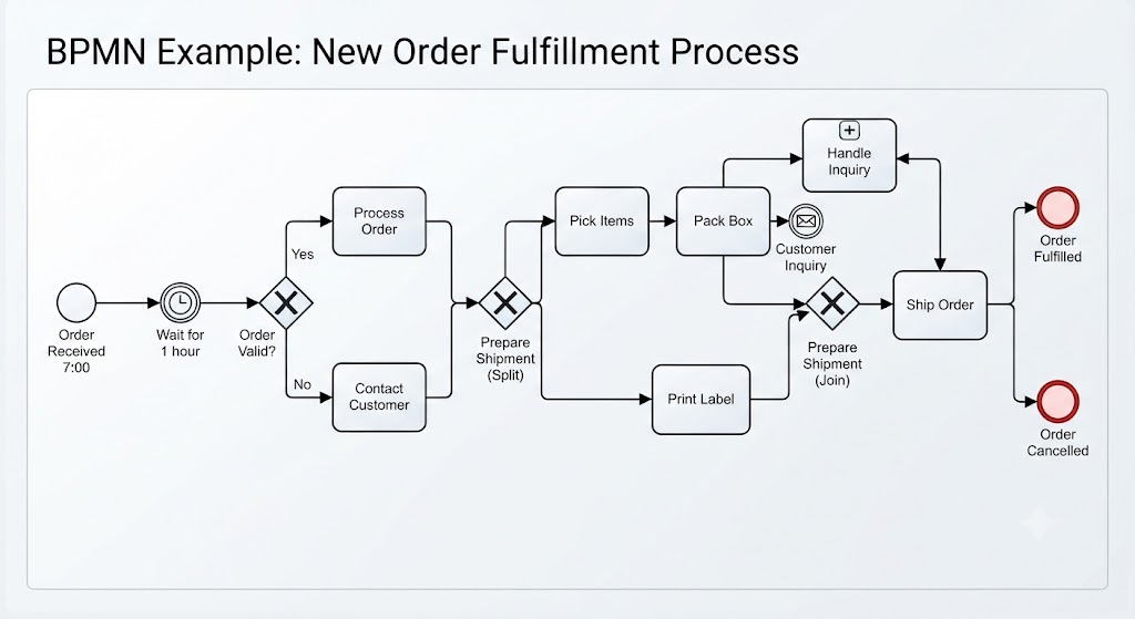
This Business Process Model and Notation (BPMN) diagram illustrates a “New Order Fulfillment” process, demonstrating how standard shapes, connectors, and gateways work together to define a workflow.
Here is a step-by-step explanation of the key concepts for beginners, based on the diagram:
1. The Flow Objects: The Core Building Blocks
The diagram is composed of three main types of flow objects that define what happens, when it happens, and how decisions are made.
-
Events (Circles): These represent “something that happens” instantly.
-
Start Event (Thin Circle): The process begins with “Order Received 7:00.“
-
End Event (Thick Red Circle): The process concludes at specific outcomes, such as “Order Fulfilled” or “Order Cancelled.“
-
-
Activities (Rounded Rectangles): These represent the work being performed.
-
Tasks: Simple, atomic units of work. For example, “Process Order,” “Pick Items,” and “Print Label” are all tasks.
-
Sub-Process (Collapsed, with ‘+’ sign): “Handle Inquiry” is a complex set of actions that is grouped into a single, simplified activity.
-
-
Gateways (Diamonds): These are decision points that control the divergence and convergence of the process flow.
2. The Flow: Connecting the Pieces
-
Sequence Flow (Solid Arrows): These arrows dictate the exact order in which activities and events occur. You must follow them from left to right to trace the process.
-
Token: Imagine an invisible “token” that starts at the “Order Received” event. It travels along the sequence flow arrows, activating one element at a time.
3. Key Process Logic: How the Diagram Works
The diagram illustrates three critical types of process flow logic:
A. Decision Making (Exclusive Gateway – XOR)
After the initial 1-hour wait, the process reaches the “Order Valid?” diamond. This is an Exclusive (XOR) Gateway, meaning only one path can be taken.
-
If the order is valid, the token follows the upper path to “Process Order.“
-
If the order is invalid, the token follows the lower path to “Contact Customer.” It is impossible for both paths to be taken simultaneously.
B. Concurrency (Parallel Gateway – AND)
After the order is processed, the flow reaches the first “Prepare Shipment” diamond with an ‘X’ (an AND symbol in this specific rendering style). This is a Parallel (AND) Gateway, used to split the flow into concurrent paths.
-
When the token arrives here, it splits into two tokens simultaneously.
-
Path 1 begins “Pick Items” (which is followed by “Pack Box”).
-
Path 2 begins “Print Label.” Both branches must complete before the flow can continue.
C. Synchronization (Parallel Gateway – AND)
Following the concurrent tasks, the two paths meet at the second “Prepare Shipment” AND Gateway.
-
The gateway waits for both incoming tokens (one from “Pack Box” and one from “Print Label”) to arrive.
-
Once both tasks are complete, the gateway “synchronizes” the flow, merging the two tokens back into a single token to proceed to “Ship Order.“
4. Managing Change (Intermediate Events)
The process includes Intermediate Events (double circles) which occur between the Start and End.
-
Timer Intermediate Event: “Wait for 1 hour” is a delay built into the flow.
-
Message Intermediate Event: The “Customer Inquiry” event shows a message (the envelope icon) arriving during the “Pack Box” step. This event is designed to interrupt the main flow, triggering the “Handle Inquiry” Sub-Process. Once the inquiry is resolved, the process resumes or restarts from a specific point.
By combining these fundamental elements—Events, Activities, Gateways, and Sequence Flow—this BPMN diagram provides a clear, standard, and unambiguous map of the entire order fulfillment process.
Conclusion
Mastering the core flow objects of BPMN—Activities, Events, and Gateways, seamlessly connected by Sequence Flow—is the critical first step toward effective business process modeling. By understanding the distinct visual cues of rounded rectangles, circles, and diamonds, and knowing when to apply specific variations like the None Task, Timer Events, or Exclusive Gateways, Business Analysts can translate complex operational realities into clear, standardized visual maps. Ultimately, leveraging these core elements allows organizations to design, analyze, and optimize their processes with clarity, precision, and universal understanding.
References
- From Narrative to Diagram: How Visual Paradigm’s AI BPMN Generator Transforms Process Modeling Workflows: How AI converts text narratives into BPMN diagrams.
- Mastering Business Process Modeling (BPMN 2.0) with Visual Paradigm’s AI-Powered Tools: Guide to mastering BPMN 2.0 using AI tools.
- Visual Paradigm BPMN Review: Bridging the Gap Between Business Logic and Technical Execution: In-depth review of Visual Paradigm’s BPMN capabilities.
- AI BPMN Business Process Diagram Generator Update: Release notes for the AI BPMN generator update.
- Understanding the BPMN Notation: A Key to Effective Business Process Modeling: Foundational guide to understanding BPMN notation.
- Visual Paradigm BPMN Tutorial: Video tutorial demonstrating BPMN features.
- Beyond Code and AI: Why Visual Paradigm Remains Essential for Professional Software Architecture: Enduring value of Visual Paradigm in software architecture.
- BPMN Activity Types Explained: Detailed explanation of different BPMN activity types.
- How AI-Powered NLP is Revolutionizing Text-to-BPMN Generation for Enterprise Process Modeling: NLP technology behind text-to-BPMN generation.
- Visual Paradigm Features: Overview of core features of Visual Paradigm.
- BPMN Diagram and Tools: Look at BPMN diagramming tools and features.
- Visual Paradigm Official Website: Official homepage for Visual Paradigm.
- Click Start AI – Technical Support: Technical support for getting started with AI features.
- Testing Visual Paradigm’s AI-Powered BPMN Diagram Generator for Real-World Process Mapping: Practical test of the AI generator for real-world mapping.
Related posts:
 Mastering Business Process Modeling: A Review of Visual Paradigm’s BPMN Capabilities
 The Comprehensive Guide to BPMN: Enhancing Efficiency and Productivity with Visual Paradigm BPMN + AI
 Mastering BPMN: A Comprehensive Guide to Business Process Modeling and Notation
 The Consultant’s Playbook: Conducting Live Process Mapping Workshops with AI