
Mastering UML Package Diagrams for Modular System Architecture
In the complex world of software engineering, managing the sheer scale of an application is a formidable challenge. Whether you are building a simple web app or a massive enterprise system, organizing code into logical, manageable chunks is critical. This is where the Package Diagram becomes an essential tool for system architects and developers. Unlike class diagrams that focus on implementation details, Package Diagrams provide a high-level “bird’s-eye view” of the system’s structure, focusing on how components interact and depend on one another.
This tutorial will guide you through the anatomy of a Package Diagram, using a real-world example of a Learning Platform to illustrate subsystems, dependencies, and abstraction.
What is a Package Diagram?
A Package Diagram is a type of UML (Unified Modeling Language) diagram that organizes related model elements into groups called packages. It is primarily used to visualize the static structure of a system and to show the dependencies between different parts of the architecture. By grouping elements, developers can reduce complexity and create a clearer mental model of the system.
Key benefits include:
- Organizing Large Models: Breaking down a monolithic application into manageable subsystems.
- Showing Module Dependencies: Clearly indicating which modules rely on others, helping to prevent circular dependencies.
- Identifying Architectural Layers: Visualizing the separation between the UI, business logic, and data layers.
Deconstructing the Architecture: The Learning Platform Example
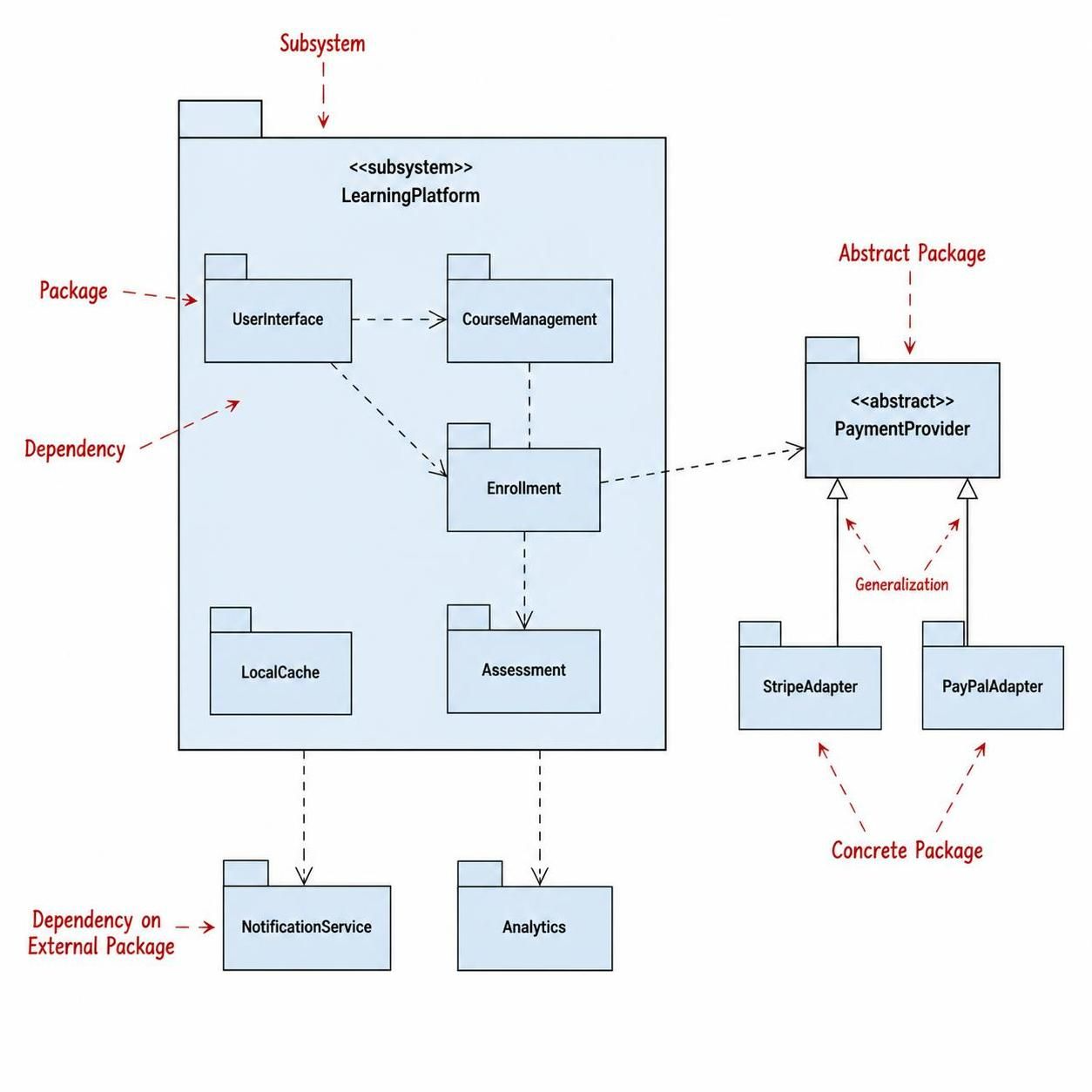
Let’s analyze the diagram provided, which depicts a LearningPlatform subsystem. This visual representation helps us understand how a complex system is decomposed.
1. The Subsystem Container
The large outer rectangle labeled <<subsystem>> LearningPlatform acts as a container. In UML, a subsystem is a package that defines a set of interfaces and can be used as a unit in a larger system. It encapsulates the core logic of the learning management system, keeping the internal details hidden from the outside world unless explicitly exposed.
2. Internal Packages and Dependencies
Inside the subsystem, we see several functional packages:
UserInterface: Handles the interaction with the user.CourseManagement: Manages the catalog of courses.Enrollment: Handles the logic of students signing up for courses.Assessment: Manages quizzes and grading.LocalCache: Likely handles data caching for performance.
The dashed arrows represent dependencies. For instance, notice the dependency from UserInterface to CourseManagement. This means the UI layer needs to access the Course Management logic to display available courses. Similarly, Enrollment depends on CourseManagement to validate if a course exists.
3. External Dependencies and Adapters
A robust system rarely exists in a vacuum. The diagram shows dependencies extending outside the main subsystem:
- External Services:
NotificationServiceandAnalyticsare external packages. The LearningPlatform relies on them to send emails and track user behavior, respectively. - Abstraction and Generalization: Look at the right side of the diagram. We see an
<<abstract>> PaymentProvider. This is a critical architectural pattern. By defining an abstract payment package, the system avoids hardcoding specific payment gateways. - Concrete Implementations: Below the abstract package are
StripeAdapterandPayPalAdapter. The solid lines with triangles indicate Generalization (inheritance). Both Stripe and PayPal adapters “inherit” from the abstract PaymentProvider, meaning they share a common interface. This allows the system to swap payment providers easily without rewriting the core enrollment logic.Modeling the Diagram
To recreate or implement this structure using standard modeling tools, you would typically use a syntax like PlantUML. Below is the code structure that generates this architecture, demonstrating how to define subsystems and relationships.
@startuml
package "LearningPlatform" as Sys {
    package "UserInterface" as UI
    package "CourseManagement" as CM
    package "Enrollment" as Enroll
    package "Assessment" as Assess
    package "LocalCache" as Cache

    UI ..> CM
    UI ..> Enroll
    CM ..> Enroll
    Enroll ..> Assess
}

package "External" as Ext {
    package "NotificationService" as Notif
    package "Analytics" as Analytics

    Sys .. Notif
    Sys .. Analytics
}

package "PaymentLayer" as Pay {
    package "<> PaymentProvider" as Provider
    package "StripeAdapter" as Stripe
    package "PayPalAdapter" as PayPal

    Stripe --|> Provider
    PayPal --|> Provider
    Enroll ..> Provider
}

@enduml
Tooling: Elevating Collaboration with Visual Paradigm
Creating and maintaining package diagrams can be tedious if done manually. This is where modern modeling tools become game-changers. Visual Paradigm, a leading enterprise modeling solution, offers a seamless integration of features that significantly boost team collaboration and productivity.
Visual Paradigm allows you to:
- Visualize Instantly: Drag and drop packages to create the structure you see in the diagram above, with automatic layout algorithms.
- Bi-Directional Engineering: Generate code skeletons from your Package Diagrams and reverse engineer existing codebases into diagrams.
- Team Collaboration: Use the repository feature to allow multiple architects to work on different packages simultaneously, resolving conflicts automatically.
- Customization: Apply custom shapes, colors, and stereotypes (like
<<abstract>>) to match your team’s specific standards.
Conclusion
Package Diagrams are more than just boxes and arrows; they are the blueprint of your software’s soul. They define the boundaries of responsibility and the flow of information. By mastering these diagrams, you can design systems that are not only functional but also maintainable, scalable, and adaptable to future changes.