
Mastering Component Modeling: Building an Online Store Architecture with VPasCode
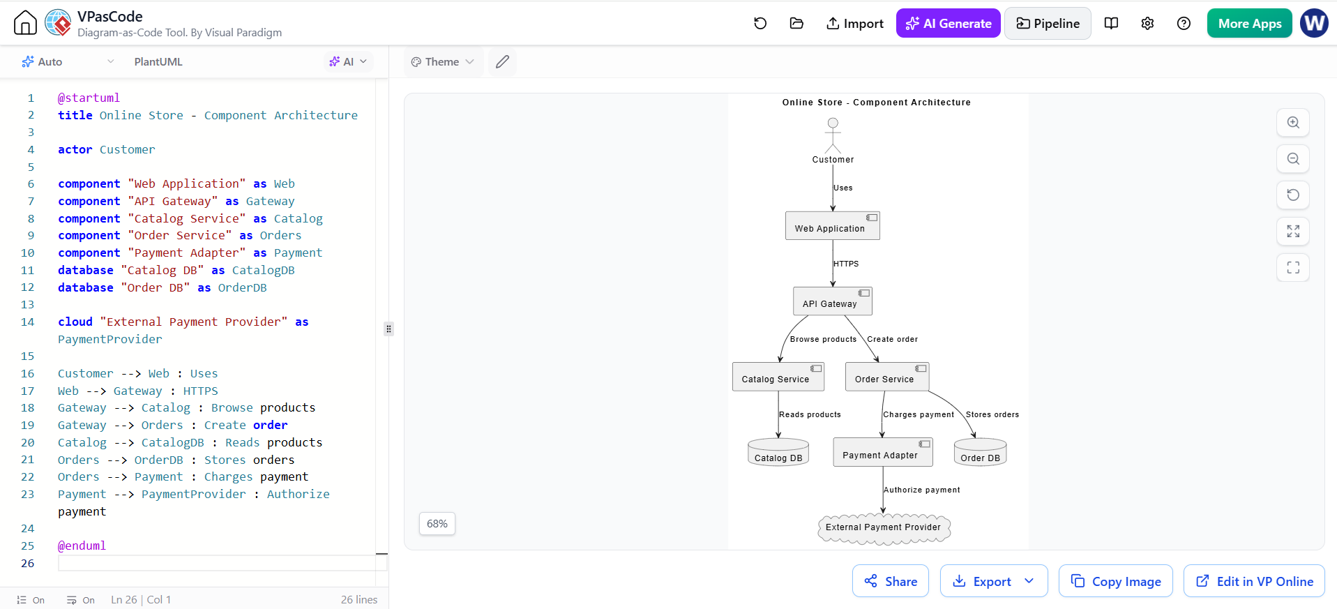
In modern software engineering, the ability to visualize system architecture is just as critical as writing the code itself. As systems grow in complexity, moving from monolithic structures to microservices requires precise documentation. This tutorial explores how to leverage PlantUML within the VPasCode environment to design a robust Component Diagram for an “Online Store” application.
This guide will walk you through the logic of defining actors, services, and databases, and how to map their interactions using the “Diagram-as-Code” approach.
Why Use Component Diagrams?
Component diagrams provide a high-level view of a system’s structure. Unlike use case diagrams that focus on user interaction, or sequence diagrams that focus on temporal logic, a component diagram focuses on modularity. It helps architects:
- Decompose a system into manageable sub-systems (e.g., “Catalog Service” vs. “Order Service”).
- Identify dependencies between components.
- Visualize the flow of data between internal services and external providers.
The VPasCode Advantage
VPasCode, the Diagram-as-Code tool by Visual Paradigm, allows developers to define visual diagrams using text. This approach offers version control compatibility and rapid iteration. By using the PlantUML syntax, you can describe complex architecture without the drag-and-drop limitations of traditional GUI tools.
Deconstructing the Architecture
Let’s break down the specific components defined in the “Online Store” example. The architecture is divided into four distinct layers: the User Interface, the Routing Layer, the Business Logic, and the Data Layer.
1. The Actor and Entry Points
The process begins with the actor, representing the human user. In our example, the Customer interacts directly with the Web Application. This is the entry point for all requests.
2. The API Gateway (Routing Layer)
Instead of the web app connecting directly to every service, we introduce an API Gateway. This acts as a single entry point for all client requests. It handles protocol translation (HTTPS) and routes traffic to the appropriate internal service based on the request type.
3. Microservices (Business Logic)
The core functionality is split into specialized components:
- Catalog Service: Handles product browsing and inventory lookup.
- Order Service: Manages the logic for creating and storing orders.
- Payment Adapter: A specialized component that abstracts the complexity of handling financial transactions.
4. Data Persistence and External Cloud
Components don’t store data in isolation. We define database components for persistent storage. Finally, we use a cloud component to represent an external entity—the External Payment Provider (like Stripe or PayPal)—which sits outside the organization’s direct control.
Step-by-Step: Writing the Code
To replicate this architecture in VPasCode, we use specific PlantUML keywords. Here is the complete source code for the diagram, demonstrating how to define relationships and data flow.
@startuml
title Online Store - Component Architecture

actor Customer
component "Web Application" as Web
component "API Gateway" as Gateway
component "Catalog Service" as Catalog
component "Order Service" as Orders
component "Payment Adapter" as Payment
database "Catalog DB" as CatalogDB
database "Order DB" as OrderDB
cloud "External Payment Provider" as PaymentProvider

Customer --> Web : Uses
Web --> Gateway : HTTPS
Gateway --> Catalog : Browse products
Gateway --> Orders : Create order
Catalog --> CatalogDB : Reads products
Orders --> OrderDB : Stores orders
Orders --> Payment : Charges payment
Payment --> PaymentProvider : Authorize payment

@enduml
Analyzing the Relationships
The power of this diagram lies in the arrows connecting the components. In PlantUML, these represent the dependencies or data flow.
- Customer –> Web (Uses): Indicates that the actor relies on the web application for access.
- Web –> Gateway (HTTPS): Shows that the web app communicates securely with the gateway.
- Gateway –> Catalog/Orders: The Gateway acts as a dispatcher. It routes “Browse” requests to the Catalog and “Create Order” requests to the Orders service.
- Service –> Database: These vertical lines (e.g.,
Catalog --> CatalogDB) represent data access. The Catalog Service reads from the Catalog DB, while the Order Service writes to the Order DB. - Orders –> Payment: When an order is created, the Order Service triggers the Payment Adapter to process the charge.
- Payment –> PaymentProvider: Finally, the adapter communicates with the external cloud provider to authorize the transaction.
Conclusion
By using VPasCode and PlantUML, you can create a self-documenting architecture that evolves alongside your codebase. The “Online Store” example demonstrates a classic microservices pattern: separation of concerns, a centralized gateway, and clear data ownership. Whether you are designing a new system or documenting an existing one, this textual approach ensures your architecture remains clear, maintainable, and visually accurate.