
C4 Modeling with AI: Mastering Software Architecture in Visual Paradigm
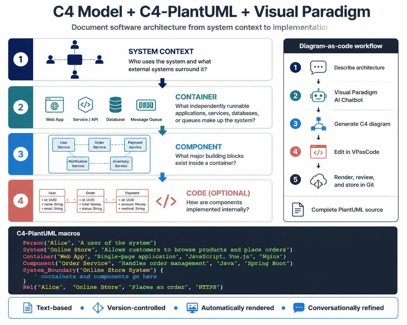
Documenting software architecture is often a balancing act between technical accuracy and readability. Too much detail, and developers get lost in the weeds; too little, and the system’s structure remains a mystery. The C4 model offers a pragmatic solution by breaking down architecture into four distinct levels of detail. When combined with Visual Paradigm’s AI capabilities and VPasCode, this modeling approach transforms from a static drawing exercise into a dynamic, version-controlled workflow.
This tutorial explores how to leverage the C4 model—from System Context down to Code—using the power of C4-PlantUML and Visual Paradigm’s conversational AI.
1. The C4 Model: A Hierarchy of Detail
The C4 model is designed to help you document software architecture at progressively lower levels of detail. Each level answers a specific question about the system, ensuring that different stakeholders get the information they need without being overwhelmed.
Level 1: System Context
The highest level of abstraction. It answers the question: Who uses the system and what external systems surround it?
- Focus: The big picture. It shows the system as a single box and its relationships with users and other systems.
- Key Elements: People (Actors), Systems, and Relationships.
Level 2: Container
This level zooms in to answer: What independently runnable applications, services, databases, or queues make up the system?
- Focus: The technology stack and major runtime environments.
- Key Elements: Web Apps, Mobile Apps, Microservices, Databases, and Message Queues.
Level 3: Component
Here we zoom in further to answer: What major building blocks exist inside a container?
- Focus: Logical cohesion within a container. It explains the responsibilities of the container’s internal parts.
- Key Elements: Services, Repositories, Controllers, and UI components.
Level 4: Code (Optional)
The most granular level. It answers: How are components implemented internally?
- Focus: UML Class diagrams or code-level logic.
- Usage: This level is optional. It is usually reserved for complex algorithms or specific implementation details that require code-level precision.
2. The Diagram-as-Code Workflow
Visual Paradigm has revolutionized the C4 modeling process by integrating AI and text-based editing. This approach ensures that your architecture diagrams are treated as code: they can be reviewed in Git, rendered automatically, and edited conversationally.
Step 1: Describe Architecture
Start by defining your system. You don’t need to be an expert in syntax yet. Simply describe the architecture in natural language.
Step 2: Visual Paradigm AI Chatbot
Input your description into the Visual Paradigm AI Chatbot. The AI interprets your requirements and suggests the appropriate C4 model structure, generating the initial diagram logic.
Step 3: Generate C4 Diagram
The AI generates the diagram based on your input. You can view the visual representation immediately to validate the relationships and structure.
Step 4: Edit in VPasCode
Refine the diagram by switching to VPasCode. This is where you can perform line-by-line edits. If the AI missed a relationship or mislabeled a container, you can fix it directly in the text source.
Step 5: Render, Review, and Store in Git
Once the diagram is finalized, the complete PlantUML source code can be stored in a Git repository. This allows for version control, code reviews, and automated rendering in your documentation pipeline.
3. Understanding C4-PlantUML Macros
C4-PlantUML extends the standard PlantUML language with specific macros tailored for architecture modeling. These macros make it easy to define the hierarchy and relationships between elements.
Here are the core macros you will encounter:
Person: Represents a user or actor interacting with the system.System: Represents a distinct system of interest.Container: Represents a runtime environment (e.g., a web app or database).Component: Represents a distinct part of a container’s code.SystemBoundary: A container that holds components, acting as a visual boundary.Rel: Defines the relationship (relationship type, source, destination, label).
Example: Creating a System Context Diagram
The following code snippet demonstrates how to define a basic “Online Store” system context using C4-PlantUML macros.
@startuml
!include

Person(Alice, "A user of the system")
System(OnlineStore, "Allows customers to browse products and place orders")

Rel(Alice, OnlineStore, "Places an order", "HTTPS")

ShowBoundary(true)
ShowRelOrigin(true)
ShowRelDestination(true)
@enduml
Example: Defining Containers and Components
To move down to the Container and Component levels, you utilize the SystemBoundary macro to group elements together.
System_Boundary(OnlineStoreSystem, "The Online Store") {
    Container(WebApp, "Single-page application", "JavaScript, Vue.js", "Nginx")

    ContainerDb(Database, "Customer Data", "SQL", "PostgreSQL")

    Container_Ext(ExternalSystem, "Third-party API", "REST API", "Python")

    Rel(WebApp, Database, "Reads/Writes", "TCP/IP")
    Rel(WebApp, ExternalSystem, "Fetches data", "HTTPS")
}

Rel(Alice, WebApp, "Interacts with", "HTTPS")Conclusion
By combining the structured clarity of the C4 model with the automation of Visual Paradigm AI and the precision of VPasCode, you can create architecture documentation that is both maintainable and insightful. Whether you are sketching the high-level System Context or diving deep into Component relationships, this workflow ensures your architecture documentation stays up-to-date with your code.