
Building an Online Order Process Context Diagram with VPasCode
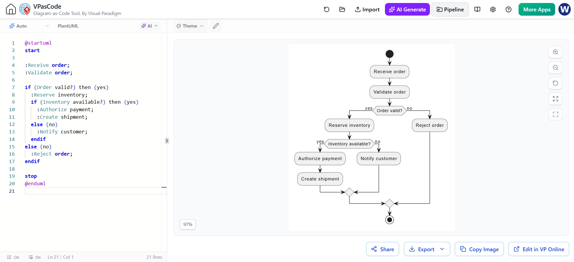
In the realm of software engineering and business process modeling, clarity is king. Whether you are a developer mapping out a checkout flow or a business analyst defining order management rules, visualizing the logic is crucial. This tutorial explores how to model a standard e-commerce order processing workflow using Activity Diagrams, specifically leveraging the power of VPasCode (Visual Paradigm as Code).
Understanding the Workflow: From Input to Fulfillment
The core of this tutorial revolves around a classic business logic scenario: processing a customer order. The workflow is not merely linear; it is a decision tree. It begins with the receipt of an order and branches out based on validation checks and resource availability (inventory).
Here is the logical breakdown of the system architecture we are modeling:
- Ingestion: The system receives an order.
- Validation: The order details are checked for correctness.
- Resource Check: If valid, the system checks if inventory is available.
- Fulfillment or Fallback:
- If inventory exists: Payment is authorized, and a shipment is created.
- If inventory is missing: The customer is notified of the delay or shortage.
- Termination: The process ends, either with a shipment created or an order rejected.
Modeling with VPasCode: The Power of “Diagram-as-Code”
Traditionally, creating these diagrams requires dragging and dropping shapes on a canvas. While effective, this approach often leads to formatting issues and makes version control (using tools like Git) difficult. VPasCode solves this by allowing you to define the entire diagram using a text-based language (PlantUML).
By writing code, you gain:
- Version Control Friendly: Diagrams become diffable text files.
- Speed: You can generate complex logic trees faster by typing than by clicking.
- Refinement: With AI-assisted features, you can describe a process, and the tool generates the code, which you then refine.
The Code Structure
Let’s dissect the syntax used to generate the diagram shown in the interface. The code below represents the exact logic described above, written in VPasCode.
@startuml
start
:Receive order;
:Validate order;
if (Order valid?) then (yes)
  :Reserve inventory;
  if (Inventory available?) then (yes)
    :Authorize payment;
    :Create shipment;
  else (no)
    :Notify customer;
  endif
else (no)
  :Reject order;
endif
stop
@enduml
Step-by-Step Logic Analysis
1. Initialization: The diagram starts with the start keyword, represented visually as a solid black circle. The first action is :Receive order;, an action node.
2. First Decision Point: The if (Order valid?) then (yes) block creates a decision diamond. The “yes” path continues into the complex logic, while the “no” path (the else block) leads directly to :Reject order;.
3. Nested Logic: Inside the “yes” branch, we encounter a second decision: if (Inventory available?). This nested structure demonstrates how VPasCode handles complex branching naturally.
4. Merging Paths: Notice how the “yes” path (Authorize/Create) and the “no” path (Notify) eventually converge. In PlantUML, this is often implicit at the end of an if/endif block, creating a merge point (fork) where all execution paths reunite before reaching the stop node.
Refining Your Diagrams
One of the standout features of the tool shown in the screenshot is the AI Generate and Refinement capability. If you are unsure of the exact syntax for a specific branching rule, you can simply describe the desired behavior to the AI assistant within the tool. It will translate your natural language request into precise PlantUML code, which you can then review and edit manually.
For example, if you wanted to add a “Retry” mechanism, you could ask the AI to “Add a loop that retries inventory reservation if it fails,” and it would generate the necessary repeat or loop syntax for you.
Conclusion
By utilizing VPasCode, you transform the tedious task of diagramming into a streamlined coding workflow. The generated diagram provides a clear, unambiguous view of the system architecture, ensuring that developers and stakeholders are aligned on the order processing logic. Whether you are validating orders or managing inventory, “Diagram-as-Code” is the modern standard for effective system documentation.