
Build C4 Context Diagrams with AI Chatbot, VPasCode, and VP Online
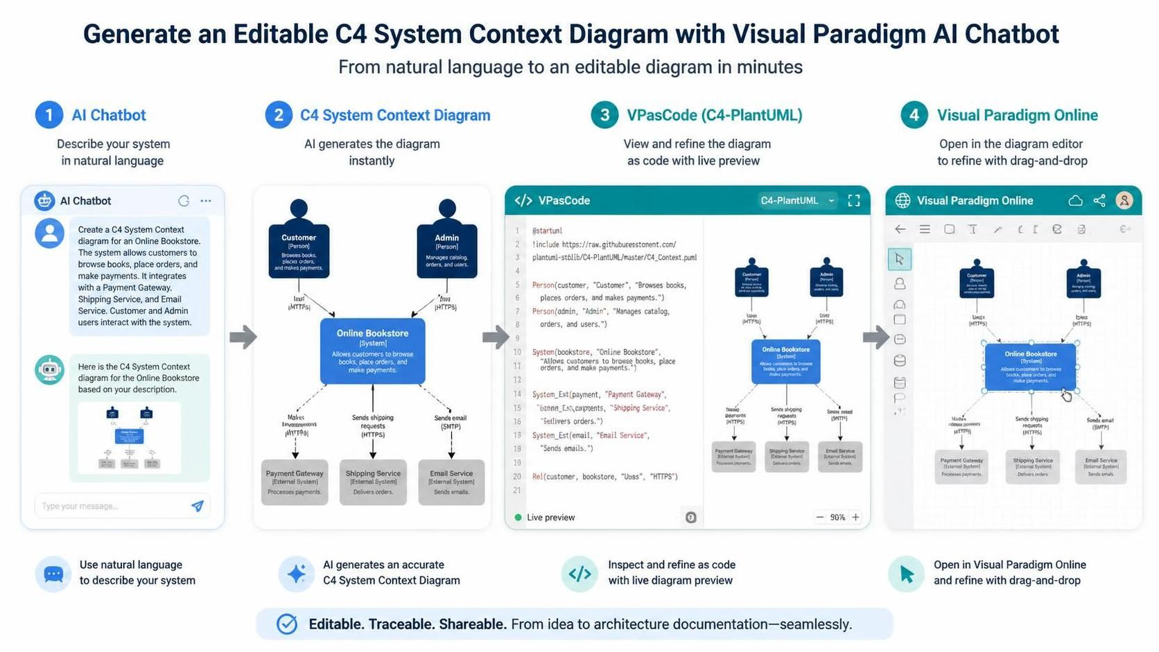
In modern software architecture, the gap between the speed of ideation and the rigor of documentation is often bridged by tools that support both natural language and formal syntax. This tutorial explores a powerful, end-to-end workflow for creating a C4 System Context Diagram using Visual Paradigm’s integrated ecosystem. By combining the AI Chatbot for rapid generation, VPasCode for code-based refinement, and the Web Diagram Editor for visual manipulation, you can produce editable, traceable architecture documentation in minutes.
Understanding the C4 System Context Diagram
Before diving into the tooling, it is essential to understand what we are building. The C4 model, created by Simon Brown, is a hierarchical approach to software architecture diagrams. The System Context Diagram is Level 1 of this model. It is the highest-level view, designed to provide context for your system to stakeholders.
A C4 Context Diagram consists of three primary elements:
- The Software System: The central box representing the application or service you are building.
- People (Actors): External users who interact with the system, such as Customers or Administrators.
- External Systems: Third-party services or legacy systems that your application integrates with, such as Payment Gateways or Shipping Services.
Step 1: Rapid Generation with AI Chatbot
The workflow begins with natural language. Instead of manually dragging boxes onto a canvas, you describe your system’s scope to the Visual Paradigm AI Chatbot. The AI interprets your prompt to identify the system, the actors, and the external dependencies.
For example, consider a scenario where you need to document a food delivery platform. You would input a description like:
“Create a C4 System Context Diagram for a Food Delivery Platform. The system allows customers to browse restaurants and place orders. It integrates with a Payment Gateway for transactions, a Mapping Service for delivery routes, and an SMS Service to notify customers of order status.”
The AI instantly generates the diagram structure, identifying the relationships and the data flows (e.g., “Sends payment,” “Delivers routes”).
Pro Tip: AI Limitations
While the AI is excellent at generating the structure, it often defaults to generic relationship labels. The generated diagram is a draft, not a final artifact. This is where the next step—refining the code—becomes crucial.
Step 2: Transitioning to VPasCode (C4-PlantUML)
Once the AI generates the diagram, the true power of the workflow emerges. Visual Paradigm allows you to export this visual representation into VPasCode, a code-based editor that uses the C4-PlantUML syntax. This approach transforms your diagram from a static image into a maintainable, text-based artifact.
Why use code for diagrams? It enables version control, easier collaboration, and precise control over labels that might be missed by AI. In the VPasCode editor, you will see the visual diagram update in real-time as you edit the code.
Inspecting the C4-PlantUML Code
Let’s analyze the syntax that was generated for our Food Delivery Platform. The code is structured to define relationships between specific IDs.
@startuml
include https://raw.githubusercontent.com/plantuml-stdlib/C4-PlantUML/master/C4_Context.puml

Person(customer, "Customer", "Browses restaurants, places orders, and makes payments.")
Person(admin, "Admin", "Manages catalog, orders, and users.")

System(food_delivery, "Food Delivery Platform", "Allows customers to browse restaurants, place orders, and make payments.")

System_Ext(payment_gateway, "Payment Gateway", "Processes payments.")
System_Ext(mapping_service, "Mapping Service", "Delivers routes.")
System_Ext(sms_service, "SMS Service", "Sends notifications.")

Rel(customer, food_delivery, "Places orders", "HTTPS")
Rel(food_delivery, payment_gateway, "Sends payment", "HTTPS")
Rel(food_delivery, mapping_service, "Sends location", "API")
Rel(food_delivery, sms_service, "Sends alert", "SMS")

@enduml
Notice the specific syntax used here:
- include: Imports the standard C4 library to ensure the shapes (like the “Person” stick figure) are rendered correctly.
- System_Ext: Explicitly tags external dependencies, distinguishing them from internal components.
- Rel: Defines the relationship between two entities, allowing you to specify the label (e.g., “Places orders”) and the protocol (e.g., “HTTPS”).
Step 3: Refinement in the Visual Diagram Editor
After refining the logic in the code editor, you can seamlessly open the diagram in the Visual Paradigm Online editor. This step is vital for final polish. The code you wrote in VPasCode acts as the “source of truth,” but the graphical editor allows for:
- Drag-and-Drop Layout: If the automatic layout is cluttered, you can manually rearrange boxes for better readability.
- Styling Adjustments: Change colors, fonts, or add notes to specific elements.
- Final Review: Ensure that the diagram accurately reflects the business requirements before sharing it with the team.
Conclusion: A Flexible Architecture Workflow
This workflow demonstrates that architecture modeling does not have to be a choice between “fast but messy” and “precise but slow.” By leveraging the AI Chatbot for the heavy lifting of structure, VPasCode for the precision of syntax, and the Web Editor for the flexibility of visuals, you create a robust documentation process.
Whether you are documenting a simple microservice or a complex enterprise ecosystem, this combination of tools ensures your diagrams are always editable, traceable, and shareable.