


1. Introduction
1.1 The Role of UML in Modern Software Development
For decades, the Unified Modeling Language (UML) has served as the standard visual language for software system design. Despite predictions of its demise in the age of agile development, UML has not only survived—it has evolved. In 2025 and beyond, UML remains a vital tool for designing complex software systems, particularly in enterprise, regulated, and large-scale environments .
The key shift in recent years has been the transformation of UML from a static, documentation-heavy practice into a dynamic, intelligent, and agile-friendly design engine. This evolution is largely driven by the integration of artificial intelligence into modeling tools, fundamentally changing the cost-benefit equation of visual modeling .
1.2 Why UML Still Matters in Agile and DevOps Environments
The long-standing belief that “UML is not agile” stems from historical misuse—specifically, Big Design Up Front (BDUF), where teams spent weeks creating detailed UML models before writing a single line of code . This approach was indeed anti-agile: maintaining models during sprints became a burden, models quickly fell out of sync with evolving code, and design changes required tedious manual edits.
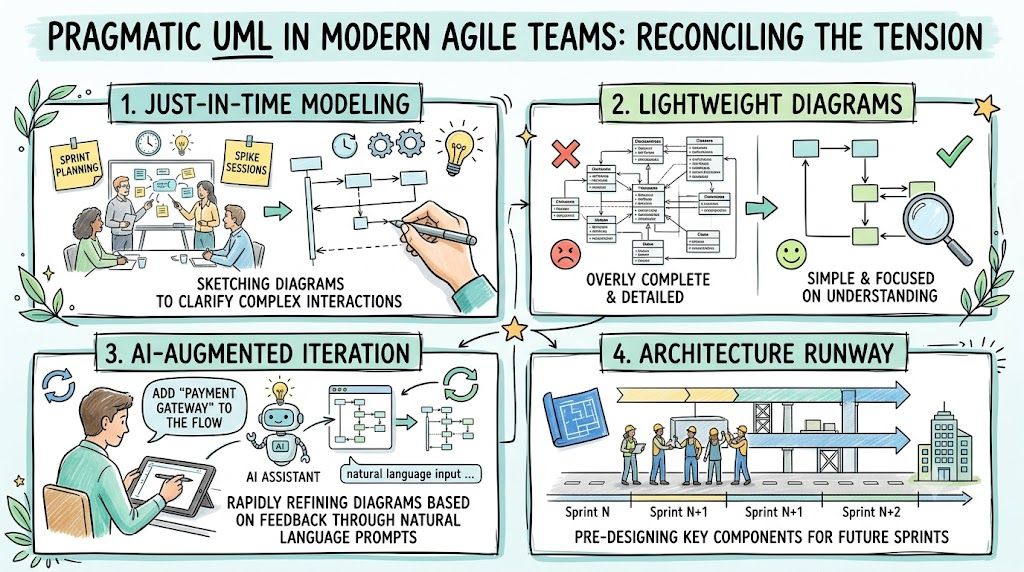
Modern agile teams have reconciled this tension through pragmatism. Instead of eliminating UML, they use lightweight, just-in-time modeling—only when it adds value . This approach includes:
-
Just-in-Time Modeling: Sketching diagrams during sprint planning or spike sessions to clarify complex interactions
-
Lightweight Diagrams: Focusing on understanding rather than completeness
-
AI-Augmented Iteration: Rapidly refining diagrams based on feedback through natural language prompts
-
Architecture Runway: Pre-designing key components for future sprints
According to the 2024 State of Software Architecture Report, 68% of enterprise teams still use UML in some form—primarily for high-level alignment and cross-team communication .
1.3 Overview of Visual Paradigm and UML Assisted Tools
Visual Paradigm has emerged as the industry leader in AI-powered visual modeling, particularly with the release of Visual Paradigm 18.0 . The platform combines comprehensive UML modeling capabilities with an AI ecosystem that fundamentally redefines what a modeling tool can be.
The AI ecosystem includes:
-
Generative AI Core: Natural language to UML conversion, code-to-diagram reverse engineering
-
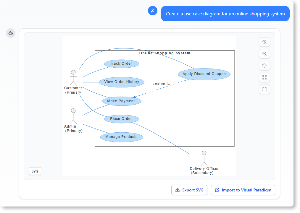
AI Chatbot Assistant: Conversational interface for design iteration and refinement
-
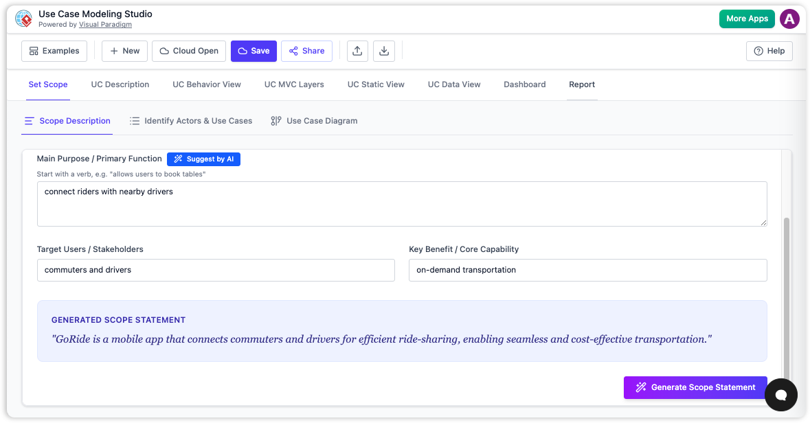
AI Use Case Modeling Studio: Automated transition from requirements to specifications
-
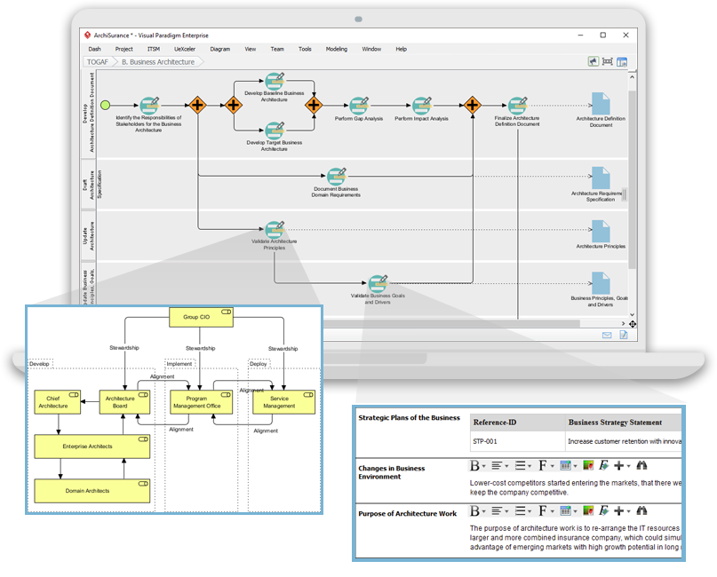
Enterprise-Grade Integration: OpenDocs for searchable architecture knowledge, TOGAF and ArchiMate support
-
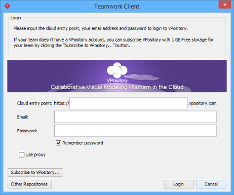
Collaboration & Version Control: Real-time co-editing
2. Understanding UML Fundamentals
2.1 What is UML? A Brief History and Evolution
The Unified Modeling Language emerged in the mid-1990s as a standardized language for communicating engineering design intent. It was adopted as an ISO standard and has since become the lingua franca of software design .

UML’s success is partially due to its role as a cognitive and communicative aid for stakeholders at various levels—management, developers, IT operations, and business analysts. The language provides utility across many domains, including healthcare, finance, and aerospace .
2.2 Core UML Diagram Types: Structural vs. Behavioral
UML diagrams fall into two broad categories:

Structural Diagrams describe the static architecture of a system:
-
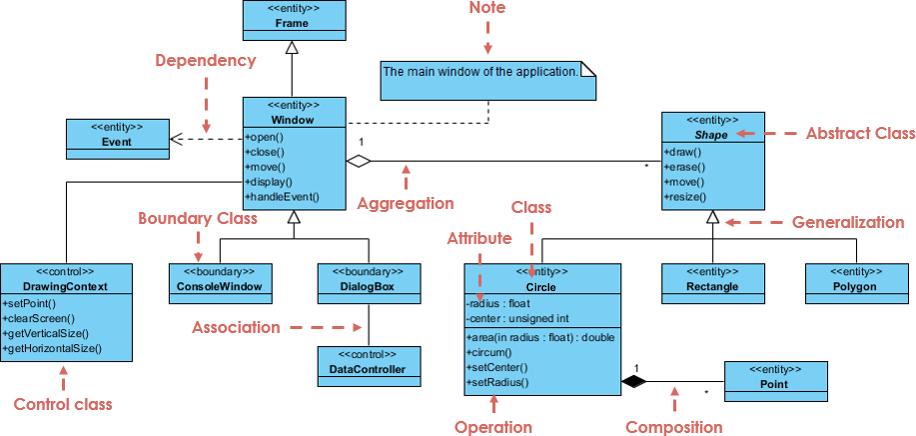
Class Diagrams: Domain entities and relationships
-
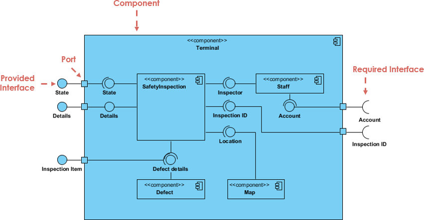
Component Diagrams: System modules and dependencies
-
Deployment Diagrams: Physical infrastructure mapping

Behavioral Diagrams describe dynamic system behavior:
-
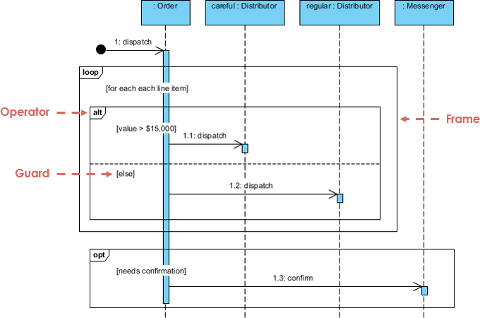
Sequence Diagrams: Interaction flows over time
-
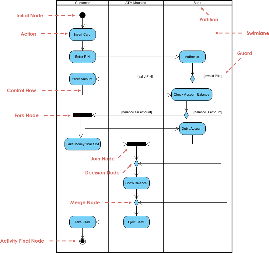
Activity Diagrams: Business processes and workflows
-
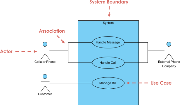
Use Case Diagrams: System functionality from user perspective
-
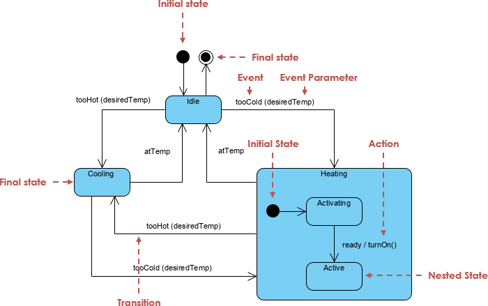
State Machine Diagrams: Object lifecycle states
2.3 When to Use UML: Identifying the Right Scenarios
UML provides the greatest value in specific contexts where clarity, communication, and design integrity are non-negotiable :
| Context | Why UML Is Valuable |
|---|---|
| Enterprise Systems | Aligns architecture across dev, QA, ops, and business teams |
| Regulated Industries | Supports audit trails and compliance (HIPAA, GDPR, SOX) |
| Complex Domain Modeling | Captures intricate business logic and state transitions |
| Onboarding & Knowledge Transfer | Accelerates team ramp-up with visual clarity |
2.4 Common Misconceptions About UML in Modern Teams
The most persistent misconception is that “UML is not agile.” As discussed, this stems from BDUF misuse rather than UML itself. Modern UML is a collaborative design tool, not a bureaucratic burden .
Another misconception is that C4 modeling—a lightweight, developer-friendly approach with growing adoption—somehow replaces UML. In reality, C4 and UML are complementary: use C4 for quick system overviews and onboarding, then drill into UML for deep analysis of complex interactions, state machines, or compliance documentation .
3. Visual Paradigm: A Comprehensive UML Modeling Platform
3.1 Key Features of Visual Paradigm
3.1.1 Multi-Diagram Support
Visual Paradigm supports the full spectrum of UML diagrams: Class, Sequence, Activity, Use Case, Component, Deployment, State Machine, Object, Package, and Composite Structure diagrams . Beyond UML, the platform also supports BPMN, SysML, ArchiMate, and C4 modeling .
3.1.2 Code Engineering: Round-Trip Engineering and Code Generation
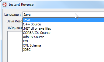
The platform enables round-trip engineering—synchronizing models with code in both directions. Add a method in Java, and the AI updates the class diagram in real time; conversely, create a class diagram, and the tool generates code stubs .
Visual Paradigm supports real-time co-editing with AI version tracking, Git integration for versioning models alongside code, and audit trails for design decisions .
3.1.4 Integration with IDEs and Version Control Systems
The platform integrates seamlessly with development workflows, supporting export to Markdown, Confluence, OpenAPI, PlantUML, and JSON .
3.2 Getting Started with Visual Paradigm
3.2.1 Installation and Setup
Visual Paradigm is available in both desktop and web versions. The desktop edition provides full control in a powerful modeling environment, while web-based access offers convenience for quick sketches and collaboration .
3.2.2 Creating Your First UML Project
The simplest way to start is through the AI Visual Modeling Chatbot. Type a natural language description, and the AI generates a complete diagram in seconds . For example:
“Build a use case diagram for an online library system where members can search for books, reserve them, borrow, return, and pay late fees.”
3.2.3 Navigating the Interface and Tool Palette
The interface supports multiple entry points: the AI Chatbot for conversational modeling, Web Apps for guided input, OpenDocs for in-document diagramming, and the full Desktop environment for precise editing .
3.3 Best Practices for Using Visual Paradigm in Team Environments
3.3.1 Standardizing Diagram Conventions
Establish team-wide standards for notation, naming conventions, and diagram granularity. The AI can help enforce these standards through smart validation and consistency checking .
3.3.2 Leveraging Templates and Reusable Components
Create and reuse component libraries for common patterns. The AI Use Case Modeling Studio can automate the transition from raw requirements to reusable use case specifications .
3.3.3 Managing Large-Scale Models
For large projects, use the model validation engine to flag inconsistencies, leverage OpenDocs as a searchable architecture knowledge base, and automate documentation generation .
4. UML Assisted: AI-Powered Modeling Assistance
4.1 Introduction to UML Assisted Technology
4.1.1 How AI Enhances UML Modeling
AI fundamentally changes the cost-benefit equation of visual modeling. Where once drawing a diagram took hours, now it takes seconds—without sacrificing quality . This shift transforms modeling from “drawing chores” to “articulation”—expressing system intent rather than fighting with tool mechanics .
4.1.2 Natural Language to UML Diagram Conversion
The AI Diagram Generator identifies entities, actors, workflows, and logical links from natural language descriptions, automatically handling positioning and formatting . It interprets semantic intent rather than just syntax, reducing initial setup time from hours to seconds.
4.2 Key Capabilities of UML Assisted
4.2.1 Automatic Diagram Generation from Text Descriptions
The Prompt-to-Diagram Generation Engine supports a wide range of diagram types. A single prompt like “Create a sequence diagram showing user login with 2FA” produces a complete, standards-compliant diagram .
4.2.2 Intelligent Suggestions for Model Completeness
The AI recommends associations, multiplicities, and inheritance in class diagrams, and suggests «include» and «extend» relationships in use case diagrams . It follows UML best practices:
-
«include» for mandatory, reusable fragments
-
«extend» for optional or conditional extensions
4.2.3 Error Detection and Consistency Checking
The AI provides real-time feedback on UML compliance and design patterns. For example: “This class has too many responsibilities—suggest refactoring,” or flags missing flow paths in activity diagrams .
4.2.4 Code-to-Diagram Reverse Engineering
Upload a codebase (Java, Python, C#), and the AI reverse-engineers a UML model, automatically detecting entities, relationships, and multiplicities .
4.3 Integrating UML Assisted into Your Workflow
4.3.1 Combining Manual and AI-Assisted Modeling
The ideal workflow is iterative: start with AI-generated drafts, then refine manually or through conversational commands. The AI handles the structural heavy lifting while engineers focus on high-level design decisions .
4.3.2 Validating AI-Generated Diagrams
While AI generates impressive drafts, domain experts should inspect whether components, relationships, and failure modes are complete and correct for the specific application . Treat AI output as reviewable artifacts, not final deliverables.
4.3.3 Iterative Refinement with Human-in-the-Loop
Refinement becomes conversational rather than graphical:
-
“Add the ‘Renew loan’ use case”
-
“Move the Librarian actor to the left side”
-
“Generate the corresponding Activity Diagram for the ‘Borrow book’ flow”
5. Practical UML Diagrams for Modern Development
5.1 Class Diagrams: Designing Robust Object-Oriented Systems
5.1.1 Modeling Domain Entities and Relationships
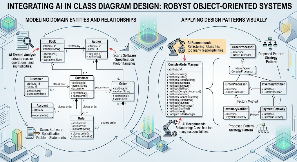
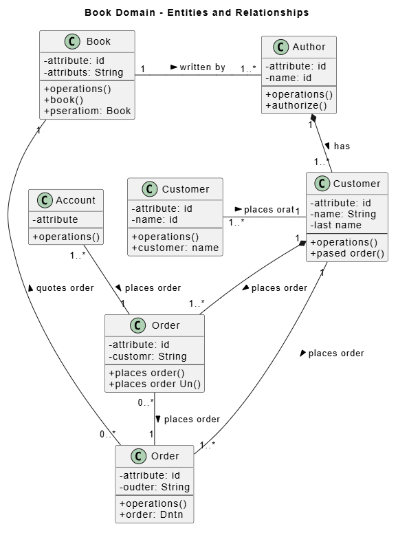
Class diagrams capture the static structure of a system. The AI Textual Analysis tool scans software specification problem statements to instantly extract candidate domain classes, operations, and multiplicities .
5.1.2 Applying Design Patterns Visually
The AI can recommend design patterns based on model analysis. For example, it might suggest refactoring when a class has too many responsibilities or propose patterns for common architectural challenges .
5.2 Sequence Diagrams: Clarifying System Interactions
5.2.1 Mapping API Calls and Service Communications
Sequence diagrams are ideal for documenting API interactions and service communications. The AI can generate these from natural language descriptions or directly from code .
5.2.2 Debugging Complex Workflows
Use sequence diagrams to debug complex workflows. The AI can “explain this sequence diagram in plain English” or “add error handling to this flow” .
5.3 Activity Diagrams: Visualizing Business Processes
5.3.1 Modeling User Journeys and Workflows
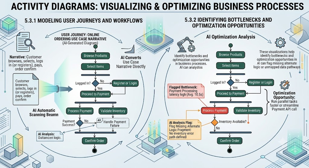
Activity diagrams map out control flows and decision logic branches. The AI can convert use case narratives directly into functional activity diagrams, ensuring behavioral aspects are accurately represented .
5.3.2 Identifying Bottlenecks and Optimization Opportunities
These visualizations help teams identify bottlenecks and optimization opportunities in business processes. The AI can flag missing alternate logic fragments or unmapped data pathways .
5.4 Use Case Diagrams: Capturing Requirements
5.4.1 Stakeholder Engagement and Requirement Validation
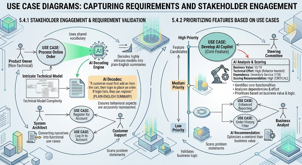
Use case diagrams provide a shared vocabulary between technical and non-technical stakeholders. The AI can decode highly intricate technical models into plain-English summaries .
5.4.2 Prioritizing Features Based on Use Cases
Use case modeling supports feature prioritization by identifying core vs. optional functionality. The AI can suggest «include» and «extend» relationships to model mandatory vs. conditional behaviors .
5.5 Component and Deployment Diagrams: Architecture Planning
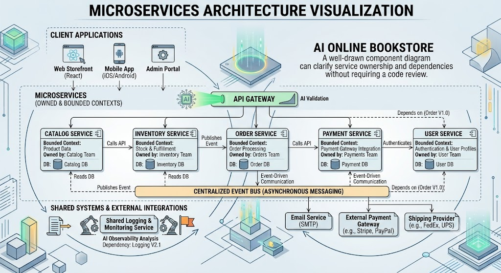
5.5.1 Microservices Architecture Visualization
Component diagrams clarify service boundaries and ownership in microservices architectures . A well-drawn component diagram can clarify service ownership and dependencies without requiring a code review.
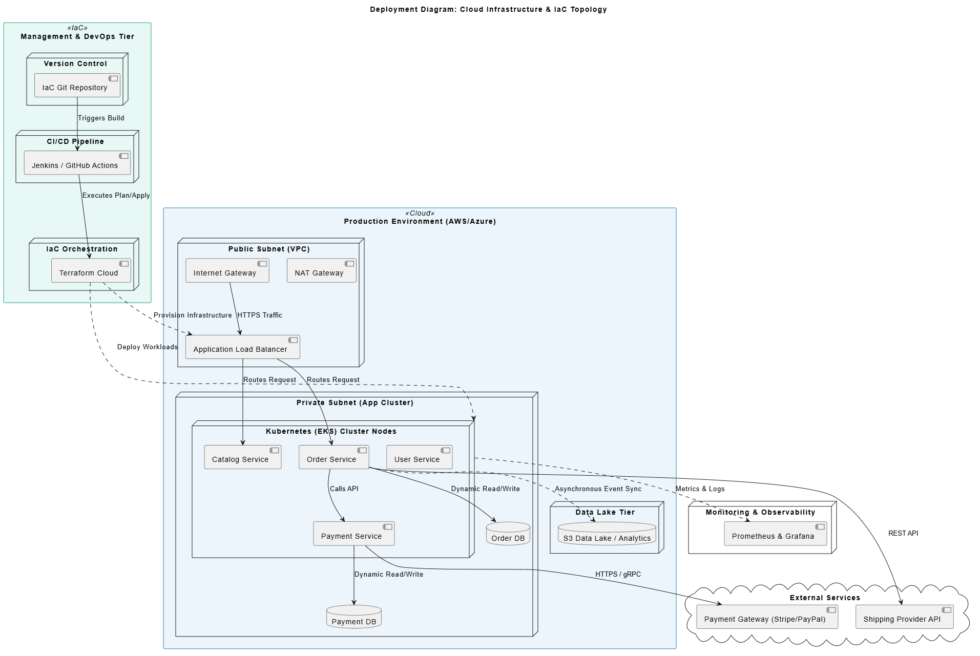
5.5.2 Cloud Infrastructure Mapping
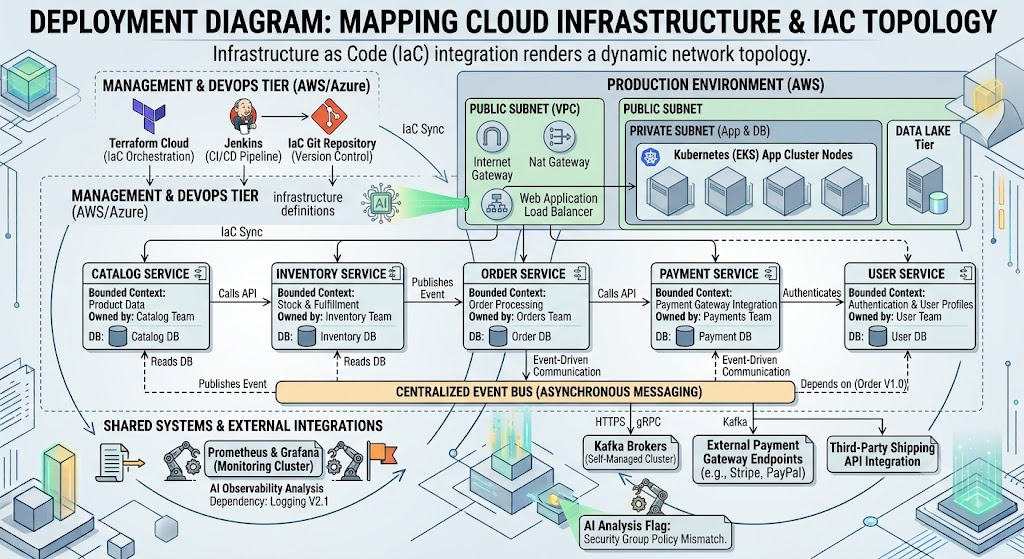
Deployment diagrams map infrastructure topology. When integrated with Infrastructure as Code, the resulting network topology can be rendered dynamically .
6. Integrating UML into Agile and DevOps Workflows
6.1 UML in Sprint Planning and Backlog Refinement
Use lightweight UML diagrams during sprint planning to clarify complex user stories or technical spikes. A quick sequence diagram during a sprint planning session can resolve ambiguity about how a payment gateway interacts with fraud detection logic .
6.2 Living Documentation: Keeping Diagrams in Sync with Code
Manual diagram maintenance fails in DevOps because it’s unreliable. Even with clear ownership, changes in code, infrastructure, or requirements break the link . The solution is treating diagrams as living artifacts integrated into the development lifecycle.
6.3 Continuous Integration with UML Models
6.3.1 Automated Diagram Updates from Code Changes
In a modern CI/CD pipeline :
-
Code is pushed to the main branch
-
CI job runs unit and integration tests
-
The modeling tool parses the code and regenerates relevant diagrams
-
Updated diagrams are committed back to the repository
-
Documentation is rebuilt using the latest model
-
Deployment proceeds only if all checks pass
6.3.2 Version Control for UML Models
Store UML files (.upml or .vp) in Git alongside source code. Use branches and pull requests. This creates a feedback loop where the model evolves with the system—no one has to remember to update it .
6.4 Bridging the Gap Between Developers and Stakeholders
6.4.1 Using UML for Effective Communication
UML diagrams remain superior for onboarding and cross-team alignment compared to raw code snippets . Visual models allow stakeholders to identify logic gaps before a single line of code is committed.
6.4.2 Reducing Ambiguity in Requirements
The AI can generate comprehensive Software Design Document reports, including project briefs, scopes, test cases, and architectural critique templates—reducing ambiguity and administrative burden .
7. Case Studies: Real-World Applications
7.1 Case Study: Enterprise Application Modernization
A Tier-1 international financial institution with 150+ developers faced challenges: a legacy core IT system with 10+ microservices, high regulatory scrutiny, frequent compliance rule changes, and a 4-6 week onboarding time for new developers .
Solution: Adopted Visual Paradigm AI for lightweight, AI-enhanced UML modeling.
-
Created a centralized model repository with AI-generated diagrams for core services
-
Used the AI chatbot to generate sequence diagrams for new compliance workflows
-
Integrated models with OpenDocs for searchable architecture knowledge
-
Enabled AI code sync so model updates reflected in code and vice versa
Results (6 months) :
| Metric | Before | After |
|---|---|---|
| Time to onboard new developer | 5 weeks | 1.5 weeks |
| Time to design new feature | 3 days | 45 minutes |
| Design miscommunications | 12/month | 2/month |
| Compliance audit prep time | 3 weeks | 1 week |
7.2 Microservices Architecture Design
For microservices projects, teams can use C4 modeling for high-level context and system overview, then drill into UML for detailed interaction analysis, state machines, and compliance documentation .
7.3 Rapid Prototyping for Startup Products
Startups benefit from AI-powered UML to quickly generate design artifacts from product requirements, enabling faster validation and stakeholder alignment .
8. Advanced Techniques and Tips
8.1 Customizing Visual Paradigm for Your Team’s Needs
Leverage the platform’s extensive customization options, including custom diagram templates, project templates, and user interface preferences.
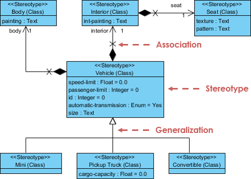
8.2 Extending UML with Profiles and Stereotypes
Use UML profiles and stereotypes to adapt UML to specific domains or industries. Visual Paradigm supports TOGAF and ArchiMate templates for enterprise architecture .
8.3 Automating Repetitive Modeling Tasks
Use the AI to automate routine tasks like:
-
Generating test cases from use cases
-
Creating database diagrams from domain models
-
Exporting models to multiple formats
8.4 Performance Optimization for Large Models
For large models, use lightweight models, cache dependencies, and run AI generation only when needed. Model regeneration typically takes seconds to minutes depending on model size .
8.5 Security and Access Control in Collaborative Modeling
Visual Paradigm provides audit trails for design decisions and Git integration for version control . Ensure proper access controls are configured for collaborative projects.
9. Common Challenges and Solutions
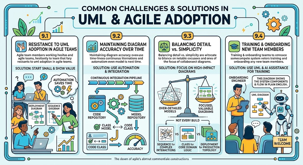
9.1 Resistance to UML Adoption in Agile Teams
Start small. Pick one diagram the team already understands—like a deployment or sequence diagram. Show how automating it saves time and prevents errors. Once they see the value, adoption grows naturally .
9.2 Maintaining Diagram Accuracy Over Time
Use automation. Store models in the same repository as code. Use validation rules to check that every class in the model has a corresponding class in the code .
9.3 Balancing Detail vs. Simplicity
Not every diagram needs to be regenerated every build. Focus on high-impact diagrams: sequence diagrams for complex interactions, class diagrams for core domain logic, deployment diagrams for production topology .
9.4 Training and Onboarding New Team Members
Use UML as part of onboarding. The AI can help new engineers understand existing models by explaining diagrams in plain English .
9.5 Tool Selection: Visual Paradigm vs. Alternatives
| Feature | Visual Paradigm (AI Ecosystem) | Generic AI Tools |
|---|---|---|
| UML Standards Compliance | Full UML 2.x, BPMN, ArchiMate, SysML | Basic shapes, limited semantics |
| Enterprise-Grade Features | Code generation, validation, governance | No support for compliance or architecture |
| AI Integration | Chatbot, model validation, code sync | Basic text-to-diagram only |
| Ecosystem | Full suite: modeling, docs, collaboration, export | Standalone diagramming |
[Citation:1]
10. Future of UML Modeling
10.1 Emerging Trends in Visual Modeling
C4 adoption has grown by 45% year-over-year, especially among startups and mid-sized tech teams . The trend is toward combining C4 for high-level context with UML for deep architectural analysis.
10.2 The Role of AI and Machine Learning in UML
According to the 2024 IcePanel State of Software Architecture Report, 60% of enterprise architects believe AI will fundamentally change how documentation is created and maintained over the next five years—likely moving toward “Architecture as Code” .
10.3 Integration with Low-Code/No-Code Platforms
AI-powered UML generation enables the use of visual modeling with low-code platforms, bridging the gap between business requirements and technical implementation .
10.4 UML Beyond Software: Business Process and System Engineering
UML is increasingly applied beyond software to business process modeling and system engineering, with support for BPMN and SysML .
Appendix – Visual Paradigm Related Resources
Key features:
-
AI Chatbot: Conversational modeling and refinement
-
OpenDocs: Searchable knowledge base with embedded diagrams
-
Doc Composer: Automated documentation generation
- Multi-Format Export: PNG, SVG, PDF, Markdown, PlantUML, JSON