

Interaction Overview Diagrams serve as a critical bridge between high-level activity flows and detailed sequence interactions. They provide a structured method to visualize the orchestration of sub-activities or interaction fragments within a larger system process. When designing complex systems, clarity in how data moves alongside control signals is paramount. This guide explores the specific mechanics of control flow and object nodes, ensuring robust system modeling without ambiguity.
The Interaction Overview Diagram is not merely a collection of boxes and arrows; it is a precise representation of logic and state. Misinterpreting how control passes between nodes or how data is buffered can lead to significant architectural flaws. We will examine the semantics of these elements, their interplay, and the patterns that define stable system behavior.
🔗 The Mechanics of Control Flow
Control flow represents the sequence of actions or the path of execution. In the context of an Interaction Overview, it dictates which sub-activity or interaction fragment executes next. This is distinct from data movement; it is about when something happens, not what data is involved.
Initial and Final Nodes
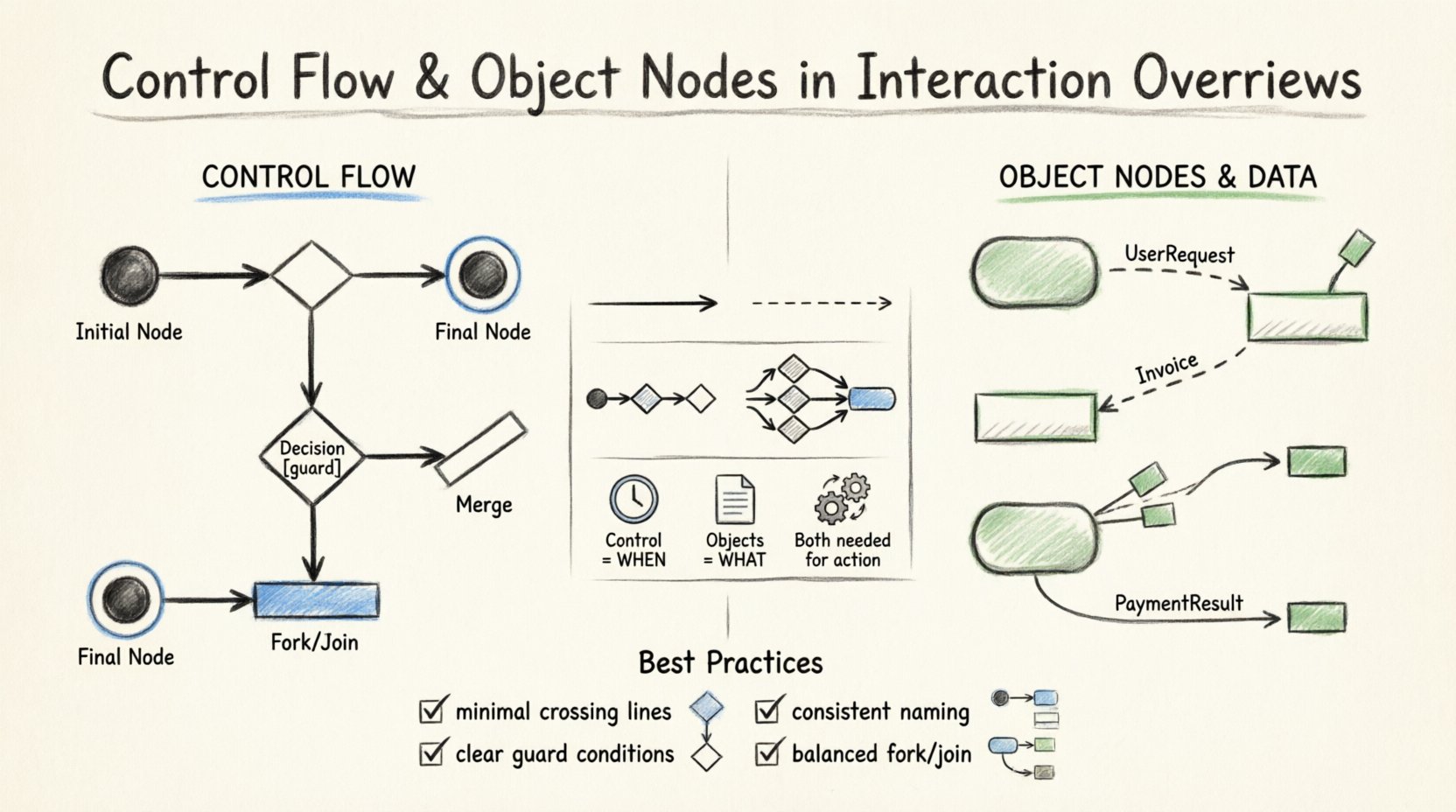
- Initial Node: Every Interaction Overview Diagram requires exactly one initial node. This is typically represented as a solid black circle. It marks the entry point where the interaction begins.
- Final Node: The diagram must terminate at a final node. This is a solid black circle with a surrounding ring. It signifies the successful completion of the interaction sequence.
It is important to note that while multiple final nodes are permissible to represent different outcomes (success vs. failure), the initial node remains singular to maintain a clear starting state.
Decision and Merge Nodes
Logic branching is a core component of any control flow. The UML specification provides specific nodes to handle this:
- Decision Node: Represented as a diamond shape. This node splits the control flow into multiple paths based on guard conditions. Each outgoing edge must have a guard condition (e.g.,
[condition = true]). If no guard is specified, the flow is assumed to be unconditional, which can lead to ambiguity. - Merge Node: Also a diamond shape, but used to combine multiple incoming paths into a single outgoing path. It does not evaluate conditions; it simply accepts any incoming control token and passes it forward.
When designing complex workflows, ensure that decision nodes are balanced with merge nodes. A decision that splits the flow into three paths should ideally have three incoming edges to a merge node to ensure all logical branches are accounted for.
Activity Edges
Edges connect these nodes. In control flow, these edges represent the transfer of control tokens. An edge originates from an output pin of one node and terminates at an input pin of another. The arrowhead indicates the direction of flow. Unlike object flows, control edges do not carry data; they signify readiness.
📦 Object Nodes and Data Semantics
While control flow manages the sequence, object nodes manage the data. In an Interaction Overview Diagram, object nodes represent the presence of information or state changes between interaction fragments. They are essential for showing how data is consumed and produced across the workflow.
Object Node Types
Object nodes can take several forms depending on the modeling intent:
- Object Pin: A small rectangle attached to an activity boundary. It acts as a source or sink for object flow.
- Object Node (Buffer): A rectangle with rounded corners. This represents a collection of objects. It can buffer multiple instances of a data type, allowing for asynchronous processing.
The distinction between a pin and a buffer is critical. Pins are transient; they exist only for the duration of the action execution. Buffers persist and can hold multiple items, allowing for queuing.
Object Flow Edges
Object flow edges connect object nodes or pins. They carry data objects from a producer to a consumer. The arrow direction indicates the flow of data. Unlike control edges, object edges do not trigger actions by themselves; they provide the necessary inputs for an action to execute.
Consider a scenario where a user request is processed. The control flow might move from Receive Request to Validate Input. The object flow, however, carries the UserRequest object from the Receive node to the Validate node. Both flows are necessary for the complete picture.
⚖️ Control Flow vs. Object Flow
Confusion often arises between control flow and object flow. While they often run in parallel, their purposes differ significantly. The table below clarifies the distinctions.
| Feature | Control Flow | Object Flow |
|---|---|---|
| Primary Purpose | Sequencing execution | Transporting data |
| Trigger | Activates actions | Provides input data |
| Node Type | Initial, Final, Decision | Object Node, Pin |
| Symbol | Solid Arrow | Dashed or Solid Arrow (with data label) |
| Concurrency | Sequential by default | Can be buffered/parallel |
Understanding this distinction prevents modeling errors. For instance, if you draw an object flow where a control token is expected, the action will not execute because it lacks the control signal. Conversely, if you send a control signal without the required data object, the action may execute but fail due to missing inputs.
🔄 Interaction Between Control and Data
In a robust Interaction Overview, control and object flows are intertwined. An action node requires both a control token to start and object tokens to function. This dual requirement ensures that the system does not process data prematurely or leave data unprocessed.
Fork and Join Nodes
Complex workflows often require parallelism. UML provides fork and join nodes for this purpose:
- Fork Node: A thick horizontal bar. It splits one incoming control flow into multiple outgoing flows. This allows multiple activities to begin simultaneously.
- Join Node: Also a thick bar. It waits for all incoming control flows to arrive before proceeding. This ensures synchronization.
When using fork and join nodes, object flows must be carefully managed. If a fork creates three parallel paths, the data produced in one path might be needed by the join. If the data is not passed correctly, the join node will wait indefinitely for a control signal that depends on data that was never generated.
Exception Handling
Real-world systems encounter errors. Interaction Overviews should account for failure paths. This is often done using exception edges or specific control paths leading to error handling nodes.
When an action fails, it may send a control token to an exception handler instead of the normal flow. Object nodes associated with the error state should contain error codes or diagnostic information. This ensures that the failure is logged and potentially recoverable.
🛠 Best Practices for Modeling
To maintain clarity and utility in your diagrams, adhere to the following principles. These guidelines help ensure that the diagram remains a valid tool for communication and analysis.
- Minimize Crossing Lines: Arrange nodes to reduce the number of intersecting edges. This improves readability significantly.
- Use Guard Conditions: Always specify guard conditions on decision nodes. Ambiguity here leads to implementation errors.
- Consistent Naming: Name object nodes and pins clearly. Use domain-specific terminology (e.g.,
Invoice,OrderStatus) rather than generic terms likeDataorInfo. - Limit Depth: Avoid nesting too many interaction fragments within a single node. Keep the overview high-level and delegate details to sub-diagrams.
- Balance Flows: Ensure that every fork has a corresponding join. Orphaned control flows can lead to deadlocks in the system logic.
🧩 Advanced Patterns and Considerations
As systems grow in complexity, standard patterns may not suffice. Advanced modeling techniques allow for greater flexibility.
Nesting Interaction Fragments
An Interaction Overview can contain interaction fragments that are themselves defined in Sequence Diagrams. This nesting allows for a multi-level view of the system. The outer diagram manages the orchestration, while the inner diagrams manage the message passing.
When nesting, ensure that the inputs and outputs of the inner fragment match the object nodes in the outer overview. Mismatched data types between levels are a common source of integration issues.
Asynchronous Communication
Some systems operate asynchronously. In these cases, object nodes can act as queues. A control flow can fire an action that places an object into a buffer, and a separate control flow can retrieve it later. This decouples the producer and consumer.
Modeling this requires explicit object nodes. Do not rely on implicit data passing. Explicit nodes make the buffering mechanism visible and allow for capacity planning.
🔍 Validation and Consistency
Once a diagram is constructed, it must be validated. This involves checking for structural integrity and logical consistency.
- Reachability: Ensure that every node is reachable from the initial node. Unreachable nodes indicate dead code or dead logic.
- Liveness: Ensure that every path eventually leads to a final node. Infinite loops without exit conditions should be explicitly marked or avoided.
- Data Consistency: Check that data types match at connection points. An integer object node cannot connect to a string input pin without a conversion action.
- Completeness: Verify that all required inputs for actions are provided by object flows. Missing inputs lead to runtime failures.
🚦 Transitioning to Implementation
The Interaction Overview Diagram serves as a blueprint for development. When developers begin coding, the control flow translates to execution logic (if/else statements, loops), while object nodes translate to variable declarations and data structures.
Clear modeling reduces the cognitive load on the engineering team. When the diagram accurately reflects the control and data dependencies, the code generated from it is more maintainable and less prone to race conditions. The visual representation acts as a contract between the design team and the implementation team.
📝 Summary of Key Components
To recap the essential elements discussed:
- Control Flow: Manages the order of execution via edges and decision nodes.
- Object Nodes: Manage data flow via pins and buffers.
- Fork/Join: Handle parallelism and synchronization.
- Interaction Fragments: Allow for detailed sequence modeling within the overview.
Mastering these components allows for the creation of precise, reliable system models. The Interaction Overview Diagram is a powerful tool when used with discipline and attention to the underlying semantics of control and data.
🔮 Future Considerations in Modeling
As software architectures evolve towards microservices and event-driven systems, the role of these diagrams remains relevant. The principles of separating control logic from data state are universal. Whether modeling a monolithic application or a distributed cloud system, the clarity provided by Interaction Overview Diagrams helps stakeholders understand the system’s behavior.
Continuous refinement of these diagrams is recommended. As requirements change, the control flow and object nodes must be updated to reflect the new reality. Keeping the models synchronized with the implementation ensures that documentation remains a valuable asset rather than a burden.
By focusing on the specific mechanics of control flow and object nodes, architects can build systems that are not only functional but also understandable and maintainable over the long term.

