


Welcome to this comprehensive guide designed for students navigating the complexities of Unified Modeling Language (UML). You have likely encountered Sequence Diagrams and Activity Diagrams. However, when system logic becomes intricate, involving loops, decisions, and multiple interaction scenarios, a different tool is required. This is where the Interaction Overview Diagram comes into play. 🧩
Many learners struggle to distinguish this diagram from others or understand when it provides value over a standard sequence model. Below, we address fifteen specific questions frequently asked in academic and professional settings. Each answer is crafted to clarify concepts without jargon overload. Let us begin.
📚 What Exactly Is an Interaction Overview Diagram?
An Interaction Overview Diagram is a specialized behavior diagram within the UML standard. It functions as a high-level overview of control flow. Think of it as a combination of an Activity Diagram and an Interaction Diagram.
- Structure: It uses nodes similar to an Activity Diagram (Action Nodes, Control Nodes).
- Content: Instead of simple actions, the nodes represent entire Interaction Diagrams (like Sequence Diagrams or Communication Diagrams).
- Flow: It shows how different interactions occur based on conditions, loops, and parallel paths.
This diagram allows you to model complex control logic without cluttering a single sequence diagram with too many alternatives.
🧩 Top 15 Student Questions About UML Interaction Overview Diagrams
1️⃣ Q: Why do I need an Interaction Overview Diagram if I have Sequence Diagrams?
Sequence Diagrams excel at detailing the step-by-step exchange of messages between objects for a single scenario. However, they struggle when you need to model complex branching logic involving multiple scenarios. 🔄
An Interaction Overview Diagram solves this by wrapping multiple Sequence Diagrams into a control flow. It acts as the director, deciding which interaction diagram runs next based on system state. It is essential for high-level architectural views where the path changes dynamically.
2️⃣ Q: What are the primary symbols used in this diagram?
The symbols are drawn from two distinct UML sets:
- Control Nodes: Initial state (filled circle), Final state (double circle), Decision diamonds (for branching), and Fork bars (for parallel processing).
- Interaction Nodes: These look like small rectangles. Inside, you place a reference to a specific Interaction Diagram.
- Flow Lines: Standard directed arrows connecting the nodes to indicate order.
3️⃣ Q: How does the flow differ from an Activity Diagram?
While they share visual similarities, the semantic difference is crucial. In an Activity Diagram, nodes represent atomic actions (e.g., “Calculate Tax”). In an Interaction Overview Diagram, nodes represent *interactions* (e.g., “User Login Process”).
Therefore, an Interaction Overview Diagram is used when the internal logic of the action is too complex to be described in a single line, requiring a detailed sequence of messages to be defined elsewhere.
4️⃣ Q: Can I use this diagram for real-time systems?
Yes, absolutely. Real-time systems often involve complex state transitions and message exchanges that depend on timing or external events. 🕒
By using an Interaction Overview Diagram, you can model the orchestration of these real-time interactions. It helps visualize how a system transitions from a waiting state to an active processing state involving multiple components.
5️⃣ Q: Is it better to draw this before or after the Sequence Diagrams?
Best practice suggests drawing the Interaction Overview first. It serves as a blueprint. 🗺️
Once the high-level flow is established, you can then flesh out the specific details in the individual Sequence Diagrams referenced by the nodes. This top-down approach prevents the common pitfall of creating a Sequence Diagram that does not fit the overall system logic.
6️⃣ Q: How do I represent a loop in this diagram?
Loops are handled using the Control Node symbols, specifically the decision diamond with a return flow. You draw a line from a decision node back to an earlier action or interaction node.
Label the loop path clearly. For example, “Retry” or “Continue”. This visualizes the iterative nature of the interaction without needing to draw the same sequence diagram repeatedly.
7️⃣ Q: What happens if an interaction fails?
You model failure paths explicitly using decision nodes. If a specific interaction node returns a failure signal, the flow can branch to an error handling interaction.
This is a key advantage. It allows you to document exception handling flows alongside the happy path, ensuring the system design accounts for potential breakdowns in communication between components.
8️⃣ Q: Can I use this to model user interface flows?
Yes. User interface flows often involve conditional logic based on user input. 🖱️
For example, a user logs in. If successful, the dashboard loads. If failed, the password reset screen appears. An Interaction Overview Diagram captures this branching logic effectively by treating the “Login” and “Password Reset” as interaction nodes.
9️⃣ Q: Does this diagram replace Use Case Diagrams?
No. They serve different purposes. A Use Case Diagram defines *what* the system does from a functional perspective (actors and goals). An Interaction Overview Diagram defines *how* the system behaves technically during those functions.
Use the Use Case Diagram for requirements gathering and the Interaction Overview for design and implementation planning.
🔟 Q: How do I handle parallel processes?
Use the Fork Node (horizontal bar). This splits the flow into multiple concurrent paths. Each path can lead to a different interaction node.
Later, you use a Join Node (another horizontal bar) to synchronize these paths before continuing. This is vital for systems that perform background tasks while waiting for user input.
1️⃣1️⃣ Q: Are there limitations to the number of interaction nodes?
There is no strict numerical limit in the UML standard, but practical readability is key. If your diagram becomes too crowded, it loses its value as an overview.
If you find yourself nesting many levels of interactions, consider splitting the diagram into subsystems or focusing on a specific module. Clarity is more important than completeness in a single view.
1️⃣2️⃣ Q: How do I reference an external diagram?
Interaction nodes usually contain a reference to a specific diagram defined elsewhere. You can label the node with the name of the Sequence Diagram it represents.
Ensure the naming convention is consistent across your project documentation. This allows stakeholders to click or navigate from the overview to the detailed sequence model easily.
1️⃣3️⃣ Q: Can I model time-based constraints here?
While Interaction Overview Diagrams focus on control flow, time constraints can be noted on the flow lines or interaction nodes. 🕰️
However, for strict timing requirements, a Timing Diagram is often more appropriate. Use the Interaction Overview to show the logical sequence, and note that specific interactions have timeouts or delays.
1️⃣4️⃣ Q: Is this diagram suitable for agile development?
Yes. Agile teams often need to visualize complex logic quickly without getting bogged down in syntax. 🚀
Because this diagram provides a macro view, it helps Product Owners and Architects understand the flow without needing to parse every message argument. It bridges the gap between high-level requirements and technical implementation.
1️⃣5️⃣ Q: What is the most common mistake students make?
The most frequent error is over-detailing the Interaction Overview. Remember, this is an *overview*. Do not put sequence details inside the nodes.
Keep the nodes abstract. If you need to show message arguments, do that in the referenced Sequence Diagrams. The overview should focus on the control flow, not the data payload.
📊 Comparison: Interaction Overview vs. Other Diagrams
Understanding where this diagram fits in the ecosystem of UML is critical. The table below clarifies the distinctions.
| Feature | Interaction Overview | Sequence Diagram | Activity Diagram |
|---|---|---|---|
| Primary Focus | Control flow between interactions | Message exchange between objects | Workflow and business logic |
| Granularity | High-level (Macro) | Low-level (Micro) | Medium to High |
| Best Used For | Complex branching logic | Single scenario details | Algorithm steps |
| Parallelism | Yes (via Fork/Join) | Limited (via combined fragments) | Yes (standard feature) |
🛠️ Implementation Guidelines for Students
To ensure your diagrams are professional and useful, follow these structural recommendations.
- Start with the Entry Point: Always begin with a clear Initial State node. This defines the starting point of the interaction.
- Use White Space: Do not cram nodes together. Allow room for flow lines to curve naturally. This improves readability significantly.
- Label Decision Nodes: Never leave a decision diamond unlabeled. Every outgoing path must have a condition (e.g., “True”, “False”, “Success”, “Error”).
- Consistent Naming: Ensure the names of interaction nodes match the titles of the referenced diagrams exactly.
- Limit Nesting: Avoid nesting interaction nodes inside other interaction nodes. Keep the hierarchy flat.
⚠️ Common Pitfalls to Avoid
Even experienced modelers can fall into traps when creating these diagrams. Be aware of the following issues.
- Creating Dead Ends: Ensure every path eventually leads to a Final State node. Unfinished flows indicate incomplete logic.
- Ignoring Exception Paths: Modeling only the success path is a common oversight. Always consider what happens if a service is unavailable.
- Mixing Concerns: Do not mix data processing logic with interaction flow logic. Keep the focus on the orchestration of interactions.
- Over-Engineering: If a simple Sequence Diagram suffices, do not force an Interaction Overview. Simplicity is preferred.
🔍 Detailed Example Scenario
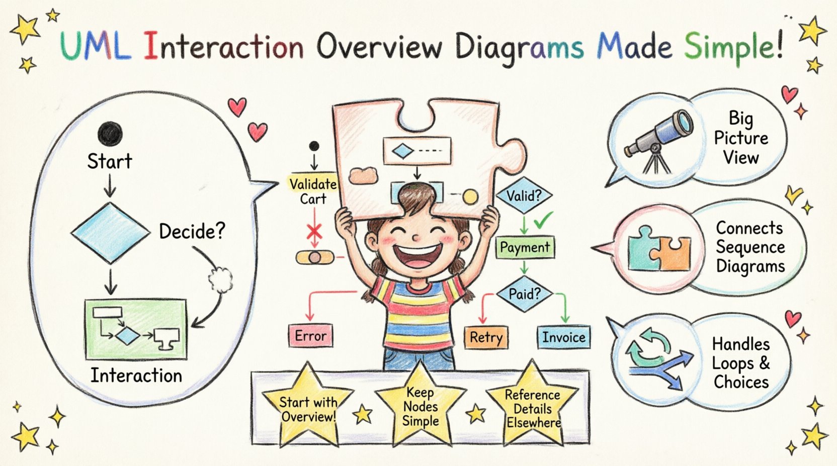
Imagine an E-Commerce checkout process. This scenario involves several steps that can branch based on payment success.
- Step 1: Initial State (Start Checkout).
- Step 2: Interaction Node “Validate Cart”.
- Step 3: Decision Node (Is Cart Valid?).
- Step 4: If No → Interaction Node “Notify Error” → Final State.
- Step 5: If Yes → Interaction Node “Process Payment”.
- Step 6: Decision Node (Payment Status?).
- Step 7: If Failed → Interaction Node “Retry Payment” → Fork to “Validate Cart”.
- Step 8: If Success → Interaction Node “Generate Invoice” → Final State.
This example demonstrates how the diagram manages the lifecycle of a transaction without listing every single API call inside the diagram itself.
📝 Summary of Key Takeaways
Mastering the Interaction Overview Diagram requires understanding its role as an orchestrator. It is not meant to replace detailed design but to provide context for it.
Key points to remember:
- It is a behavior diagram.
- It combines Activity and Interaction logic.
- It manages complex branching and loops.
- It references other diagrams for detail.
- It is vital for system architecture.
By answering these fifteen questions, you now possess the foundational knowledge to apply this tool effectively in your academic projects and future careers. Remember to prioritize clarity over complexity. A diagram that is easy to understand is worth more than one that is technically perfect but confusing.
Continue practicing by modeling real-world scenarios you encounter. The more you use it, the more natural the flow of control will become in your thinking. Happy modeling! 🎨

