


The Unified Modeling Language (UML) provides a standardized visual language for specifying, constructing, and documenting the artifacts of software systems. Among the behavioral diagrams, the Interaction Overview Diagram (IOD) often sits in the shadow of more popular siblings like the Sequence Diagram or the Activity Diagram. Despite its utility in modeling complex control flows across multiple interactions, misconceptions persist regarding its purpose, syntax, and applicability. This guide addresses common misunderstandings to clarify when and how to apply this specific diagram type effectively.
Understanding the nuances of modeling language helps teams communicate architecture without ambiguity. Many practitioners treat diagrams as static documentation, but the IOD is dynamic by nature. It captures the orchestration of interactions rather than the linear sequence of messages. By dispelling common myths, you can leverage this diagram to improve system clarity and reduce design errors.
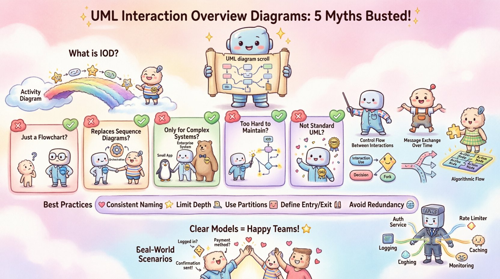
🔍 What Is an Interaction Overview Diagram?
An Interaction Overview Diagram is a type of activity diagram that is specialized for modeling the control flow of interactions between objects. It combines the high-level flow of an Activity Diagram with the detailed communication details of an Interaction Diagram (typically a Sequence Diagram).
Think of it as a bridge. It allows you to define the overall process flow while referencing specific interaction sequences without cluttering the main view. This separation of concerns is critical for maintaining large-scale system designs.
❌ Myth 1: It Is Just a Flowchart
Many developers mistake the IOD for a generic flowchart because both use decision nodes and control flow. However, the IOD adheres to strict UML behavioral semantics that distinguish it from standard business process modeling.
- Control Flow Nodes: The IOD uses specific nodes like Initial Node, Decision Node, Fork Node, and Join Node. These are standard activity diagram elements but are applied to interaction contexts.
- Interaction Fragments: Unlike a flowchart, an IOD references Interaction Use nodes. These nodes act as placeholders for entire sequence diagrams or other interaction diagrams.
- Object Flow: While flowcharts track data states, IODs track the lifecycle of interactions between system components.
If you use a standard flowchart to map system logic, you lose the context of object communication. The IOD forces you to consider how messages are exchanged during the control flow, not just the state changes.
❌ Myth 2: It Replaces Sequence Diagrams
A common error is assuming that because the IOD shows interactions, it can stand alone. This is incorrect. The IOD is an orchestration layer, not a detailed exchange layer.
- Granularity: Sequence Diagrams show the exact timing and order of messages between lifelines. The IOD abstracts this into an Interaction Use node.
- Nesting: An IOD typically references multiple Sequence Diagrams. Removing the Sequence Diagrams would leave the IOD empty of actionable detail.
- Readability: Trying to draw every message on an IOD makes it unreadable. The purpose is to summarize the flow of interactions, not detail every packet.
Use the IOD when you need to show the top-level logic that decides which sequence of events occurs next. Use Sequence Diagrams when you need to validate the internal logic of a specific step.
❌ Myth 3: It Is Only for Complex Systems
Some teams reserve the IOD for enterprise-level applications with thousands of microservices. This limits the diagram’s utility. Even small systems benefit from clear interaction orchestration.
- Scalability: Small systems often grow. Starting with an IOD ensures the architecture is designed for flow control from the beginning.
- Clarity: For simple systems, a Sequence Diagram can become convoluted if there are conditional branches. An IOD simplifies these branches visually.
- Maintainability: When requirements change, it is easier to update an IOD flow than to refactor multiple Sequence Diagrams.
Do not wait for complexity to strike before introducing the IOD. Introduce it when the flow of control becomes non-linear or when multiple interaction paths exist.
❌ Myth 4: It Is Too Hard to Maintain
There is a belief that maintaining diagrams requires constant updates that drain developer time. While diagrams can become outdated, the IOD structure actually aids maintenance if used correctly.
- Reference Stability: Since the IOD references other diagrams (via Interaction Use nodes), changes to the internal logic of a sequence do not require changes to the IOD.
- Version Control: Diagram files can be stored in version control systems. Changes to the IOD are discrete updates to the control flow logic.
- Automation: Many modeling environments allow code generation from diagrams. If the IOD is accurate, it reduces the gap between design and implementation.
The maintenance burden increases only if the diagrams are treated as separate documents rather than integrated design artifacts. Integrate them into the development lifecycle.
❌ Myth 5: It Is Not Standard UML
Some practitioners believe the IOD is a proprietary extension or a non-standard tool feature. This is false. The Interaction Overview Diagram is a core part of the UML 2.x specification defined by the Object Management Group (OMG).
- Standard Compliance: It is defined in the UML 2.5 specification under Behavioral Diagrams.
- Tool Support: Almost all professional modeling tools support the IOD syntax and semantics.
- Interoperability: Using a standard diagram type ensures that documentation can be shared across teams and tools without loss of fidelity.
Reliance on non-standard diagrams creates silos. Stick to the UML standard to ensure long-term documentation portability.
📊 Comparison: IOD vs. Sequence vs. Activity
Understanding where the IOD fits requires a clear comparison with its closest neighbors in the UML family.
| Diagram Type | Primary Focus | Key Nodes | Best Used For |
|---|---|---|---|
| Interaction Overview Diagram | Control flow between interactions | Interaction Use, Decision, Fork | Orchestrating high-level message sequences |
| Sequence Diagram | Message exchange over time | Lifelines, Messages, Activation Bars | Detailing specific interaction logic |
| Activity Diagram | Algorithmic flow and logic | Action Nodes, Control Flow, Object Nodes | Modeling business processes or algorithms |
Notice that the IOD sits between the Activity Diagram (logic) and the Sequence Diagram (detail). It acts as the glue that connects them.
🛠️ Implementation Best Practices
To ensure your Interaction Overview Diagrams remain effective and clear, follow these technical guidelines.
- Consistent Naming: Name your Interaction Use nodes clearly, such as Validate User or Process Order. This makes the IOD readable without clicking into the referenced diagram.
- Limit Depth: Do not nest Interaction Use nodes inside other Interaction Use nodes indefinitely. Keep the nesting shallow to maintain readability.
- Use Partitions: Use swimlanes (Partitions) to show which subsystem or component is responsible for the interaction.
- Define Entry and Exit: Ensure every Interaction Use node has a clear entry point and exit condition.
- Avoid Redundancy: Do not duplicate logic. If a sequence is used in multiple places, reference the same diagram rather than creating duplicates.
🌍 Real-World Scenarios
Consider how this diagram applies to common software engineering challenges.
Scenario 1: E-Commerce Checkout
In a checkout process, the system must handle multiple paths. The user might have a coupon, might not have an account, or might choose a specific shipping method.
- Initial Node: User clicks Checkout.
- Decision Node: Is the user logged in?
- Interaction Use: If yes, call LoginSequence. If no, call GuestCheckoutSequence.
- Fork Node: Parallel processing of Inventory Check and Payment Validation.
- Join Node: Wait for both to complete.
- Decision Node: Was payment successful?
- Final Node: Order Confirmation.
This structure is clearer than trying to draw every message for login, guest check, inventory, and payment in a single Sequence Diagram.
Scenario 2: API Gateway Routing
An API Gateway must route requests based on headers or user roles. An IOD helps visualize the routing logic.
- Initial Node: Request received.
- Decision Node: Check Authentication Token.
- Interaction Use: Call AuthCheckSequence.
- Decision Node: Is token valid?
- Fork Node: Route to AdminService or UserService based on role.
- Final Node: Response sent.
This ensures that the routing logic is documented separately from the internal service logic.
🔗 Integrating with Other Diagrams
The IOD does not exist in isolation. It integrates with other UML diagrams to form a complete behavioral model.
- Class Diagram: The Interaction Use nodes reference objects defined in the Class Diagram. Ensure class names match exactly.
- State Machine Diagram: Use State Machine Diagrams for the internal logic of a specific state, and use the IOD to transition between those states.
- Component Diagram: Map the Interaction Use nodes to specific components. This helps in deployment planning.
📈 Evaluating Effectiveness
How do you know if your Interaction Overview Diagram is working? Look for these indicators.
- Clarity: Can a new developer understand the flow without reading code?
- Completeness: Are all major decision points covered?
- Consistency: Do the referenced Sequence Diagrams match the IOD labels?
- Utility: Is the diagram used during code reviews or planning sessions?
If the diagram is only created once and never referenced again, it has failed its purpose. It must be a living document that evolves with the code.
🚧 Common Pitfalls to Avoid
Avoid these mistakes to keep your design robust.
- Over-Abstraction: Do not hide so much detail that the logic becomes opaque. Keep enough detail to be actionable.
- Inconsistent Notation: Stick to the UML 2.x standard. Do not invent custom symbols.
- Ignoring Error Paths: Ensure that exception handling is modeled in the IOD. It is not enough to model the happy path.
- Lack of Versioning: If you change the IOD, update the timestamp and version number. Track changes over time.
🔧 Technical Details of Control Flow
Deep dive into the mechanics of the IOD control flow.
- Control Flow: The arrows connecting nodes represent the flow of control. They are directed.
- Guard Conditions: You can add guard conditions to decision nodes (e.g.,
[user is admin]). This ensures clarity on branching logic. - Object Flow: While less common in IODs than Activity Diagrams, you can pass objects between Interaction Use nodes if the data needs to be visible.
- Interruptible Regions: You can define regions that are interruptible by events, allowing for timeout scenarios or cancellation handling.
📝 Documentation Standards
Maintain a consistent standard for your diagrams to ensure team alignment.
- Header Information: Include diagram name, version, author, and date.
- Legend: If you use custom symbols or specific notations, provide a legend.
- References: Always link to the referenced Sequence Diagrams.
- Comments: Use comments to explain complex logic that cannot be represented by symbols.
🌟 Final Thoughts on Diagram Utility
The Interaction Overview Diagram is a powerful tool for system architects. It provides a high-level view of interaction orchestration without getting bogged down in message details. By avoiding the myths discussed above, you can utilize this diagram to create clearer, more maintainable system designs.
Focus on the flow of control, not just the exchange of messages. Ensure your diagrams are standards-compliant and integrated into your development workflow. When used correctly, the IOD reduces ambiguity and improves communication across development teams.
Start applying these principles today. Refine your models, validate your assumptions, and build systems that are easier to understand and maintain. The investment in clear modeling pays dividends in reduced defects and faster onboarding for new team members.

