


Interaction Overview Diagrams (IODs) serve as critical blueprints for complex system behaviors. They map out the sequence of operations, conditional logic, and data transitions that drive software functionality. When these diagrams contain errors, the consequences ripple through development, testing, and deployment phases. Broken flows lead to unreachable states, while ambiguous guards create unpredictable runtime behavior. This guide provides a deep dive into identifying, diagnosing, and resolving structural issues within your diagrams. We will focus on logical integrity, connection validity, and condition clarity without relying on specific tools or proprietary terminology.
Ensuring diagram fidelity is not merely an aesthetic exercise; it is a fundamental requirement for system reliability. A diagram with a broken flow implies a path where the system should go but cannot. A diagram with an ambiguous guard implies a path where the system goes, but the logic determining that path is unclear. Both scenarios introduce technical debt that accumulates over time. By adhering to rigorous validation standards, teams can maintain clarity and reduce the risk of defects in the final product.
🧩 Understanding Flow Integrity in Interaction Overview Diagrams
Flow integrity refers to the continuity and correctness of the paths connecting nodes within a diagram. Every node represents an activity, decision, or event, and every edge represents a transition. For a diagram to function logically, every node must be reachable, and every path must lead to a valid termination or continuation point.
🚫 Common Causes of Broken Flows
Broken flows often arise from manual errors during the modeling process or from asynchronous updates that were not reflected across the entire diagram. Below are the primary categories of flow disruption:
- Orphaned Nodes: An activity node exists in the diagram but has no incoming or outgoing edges. This isolates the node, making it unreachable from the start point and preventing it from passing control to subsequent steps.
- Missing Transitions: A decision node requires multiple outgoing paths to handle different outcomes, but one or more paths are missing. This forces the system into an undefined state when a specific condition is met.
- Circular Dependencies: While loops are valid, unintended circular flows can cause infinite execution states. If a path leads back to a previous node without a terminating condition, the flow becomes trapped.
- Dangling Edges: An edge connects to a node on one side but leaves the other side open, terminating in empty space. This indicates an incomplete connection definition.
- Disconnected Components: The diagram is split into two or more isolated subgraphs. The main flow does not connect to the subgraph, rendering the subgraph irrelevant to the overall process.
👀 Visual Indicators of Flow Issues
Recognizing broken flows often begins with visual inspection. Look for the following signs:
- Nodes that appear floating without clear entry or exit lines.
- Lines that change color unexpectedly, often indicating a broken reference.
- Edges that intersect other edges without a defined intersection node.
- Start nodes with no outgoing edges.
- End nodes with no incoming edges.
🔍 Decoding Ambiguous Guards in Logic Paths
Guards are conditions attached to transitions that determine whether a path can be taken. They act as filters, ensuring that control flows only along the intended route based on data states. Ambiguity in guards occurs when the logic is too vague, conflicting, or incomplete.
⚠️ Types of Guard Ambiguity
Ambiguity introduces uncertainty into the execution model. Developers and testers cannot predict which branch will execute under specific circumstances.
- Overlapping Conditions: Two guards on different outgoing paths evaluate to true simultaneously. For example, one path requires “status = active” and another requires “status = pending”, but the system allows a state where both might theoretically apply if the data is malformed.
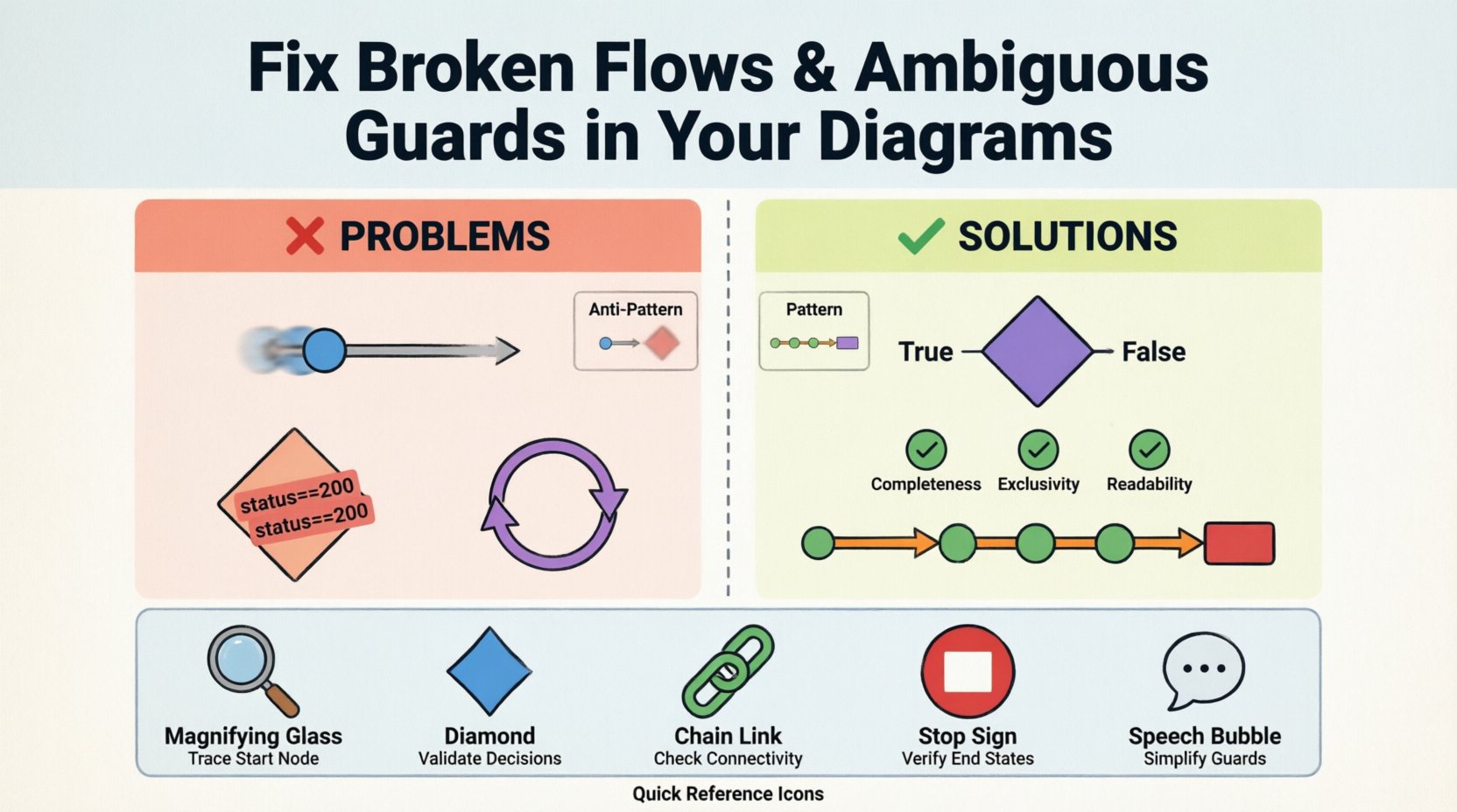
- Missing Negations: A decision node has a “True” path but lacks a “False” or “Else” path. If the condition fails, the system halts because no valid transition exists.
- Complex Boolean Logic: Using deeply nested logic (e.g., “(A OR B) AND (C OR NOT D)”) makes it difficult for humans to verify correctness. Simplification is often required to ensure clarity.
- Undefined Variables: Guards referencing data variables that are not defined in the current scope. This leads to runtime errors or default behaviors that were not intended.
- Redundant Checks: Multiple guards checking for the exact same condition without distinction. This confuses the logic hierarchy and makes maintenance harder.
📊 Guard Validation Checklist
To ensure guards are robust, apply the following validation criteria to each decision node:
- Completeness: Do all possible outcomes of a decision have a corresponding path?
- Exclusivity: Do the conditions prevent multiple paths from being valid at the same time?
- Readability: Is the condition written in plain language or simple boolean logic that a non-expert can understand?
- Data Consistency: Do the variables in the guard exist and have the correct data types?
- Default Handling: Is there a fallback path for unexpected data values?
🔧 Systematic Troubleshooting Steps
Resolving diagram issues requires a methodical approach. Random edits often introduce new errors. Follow this structured workflow to audit and repair your diagrams effectively.
1. Trace the Start Node
Begin at the entry point of the interaction overview. Verify that the start node has exactly one outgoing edge. Trace this edge to the next node. If the edge is missing, re-establish the connection. If there are multiple edges, determine which is the primary path and ensure others are conditional.
2. Validate Decision Points
At every diamond-shaped decision node, list all outgoing edges. Assign a label to each edge representing the condition. Check if the sum of these conditions covers the entire domain of the decision variable. If a path is missing, add an “Else” or “Default” transition.
3. Check Node Connectivity
Perform a graph traversal to ensure every node is reachable from the start node. Use a depth-first search approach mentally or via script. If a node is not reachable, it is an orphan and should be removed or connected to the main flow.
4. Verify End States
Ensure that every logical path terminates at an end node. If a flow ends at a node without an explicit termination symbol, the system may hang or behave unexpectedly. Add termination nodes where necessary.
5. Review Guard Expressions
Revisit every guard condition. Simplify complex boolean statements. Replace ambiguous terms like “valid” or “good” with specific data checks like “status == 200” or “value > 0”.
📋 Common Patterns vs. Anti-Patterns
Understanding what to avoid is as important as knowing what to do. The table below contrasts healthy diagram structures with common pitfalls.
| Pattern Type | Healthy Structure | Anti-Pattern (Avoid) |
|---|---|---|
| Decision Logic | Clear True/False paths with explicit labels. | Unlabeled lines or implied logic. |
| Flow Continuity | Linear progression with defined branching. | Skip connections or jumping between distant nodes. |
| Complexity | Decomposed into sub-diagrams for clarity. | One massive diagram with 50+ nodes. |
| Termination | Every path ends at a specific stop symbol. | Paths that drift into empty space. |
| Variables | Variables defined before use in guards. | Guards referencing undefined or external state. |
| Feedback Loops | Controlled loops with clear exit conditions. | Unconditional loops or missing exit paths. |
🛡️ Automation and Validation Strategies
While manual review is essential, relying solely on human inspection can miss subtle logic errors. Incorporating automated checks can significantly improve diagram quality.
🤖 Static Analysis
Static analysis tools can parse the diagram structure without executing the system. These tools check for:
- Syntax errors in guard expressions.
- Missing connections between defined nodes.
- Cycles that exceed a defined depth limit.
- Nodes that do not conform to the diagram schema.
🧪 Model-Based Testing
Model-based testing uses the diagram to generate test cases. If a path is broken, the test generation will fail, highlighting the issue immediately. This approach ensures that the diagram matches the implementation logic.
🔄 Version Control Integration
Store diagrams in version control systems. When changes are made, review the diff to see if new edges were added or existing ones removed. This history helps identify when and how a flow became broken.
🔍 Deep Dive: Handling Exception Flows
One of the most common sources of ambiguity is the handling of exceptions. A standard flow assumes everything works perfectly. Real systems encounter errors. Failing to diagram exception paths leads to broken flows when things go wrong.
🚨 Explicit Error Handling
Every major activity node should have an associated error path. If a step fails, the flow should transition to a recovery node or a termination node, not continue to the next step.
- Try-Catch Blocks: Map these to specific nodes in the diagram. The “Catch” path represents the error flow.
- Timeouts: If an operation takes too long, the guard should trigger a timeout state.
- Validation Failures: If data validation fails, the flow should loop back to input or exit to an error screen.
🔄 Retry Mechanisms
Sometimes errors are transient. A diagram might include a retry loop. Ensure this loop has a maximum count. Without a limit, a transient error could cause an infinite loop, breaking the flow.
🛠️ Maintenance and Refactoring
Diagrams are living documents. They must evolve as the system changes. However, refactoring introduces risk. Changing a diagram can break existing assumptions held by developers and testers.
📝 Refactoring Guidelines
When modifying a diagram, follow these rules to maintain integrity:
- Isolate Changes: Do not modify multiple nodes in a single change request. Test each modification independently.
- Update Documentation: If a flow changes, update the accompanying text documentation to match.
- Notify Stakeholders: Ensure all teams using the diagram are aware of structural changes.
- Preserve Semantics: Do not change the meaning of a node, even if you rename it. The logic must remain consistent.
🧹 Regular Audits
Schedule regular audits of your diagram library. Over time, legacy diagrams accumulate errors that were never fixed. A quarterly review can catch:
- Deprecated nodes that are no longer used.
- Stale guard conditions referencing removed features.
- Broken links from external references.
- Inconsistent naming conventions.
🌐 Impact on System Performance and Stability
Broken flows and ambiguous guards are not just documentation errors; they directly impact system performance and stability.
⚡ Runtime Performance
Complex, ambiguous guards force the runtime engine to evaluate more conditions than necessary. Simplifying logic reduces computational overhead. A broken flow might cause the system to wait for a signal that never arrives, leading to latency.
🛑 Stability Risks
Unreachable code paths often hide critical bugs. If a guard is ambiguous, the system might take a path that was not tested. This leads to instability in production environments where edge cases are more common.
📉 Technical Debt
Every uncorrected diagram error increases technical debt. Developers spend time debugging issues that could have been caught during the modeling phase. Clear diagrams reduce the time required to onboard new team members.
📈 Measuring Diagram Quality
To ensure continuous improvement, define metrics for diagram health. Tracking these metrics helps identify trends and areas requiring attention.
- Connectivity Rate: Percentage of nodes that are reachable from the start node.
- Guard Completeness: Percentage of decision nodes with all paths defined.
- Complexity Score: Average number of nodes per diagram. High scores indicate a need for decomposition.
- Validation Errors: Number of errors found during automated validation.
🤝 Collaborative Modeling Best Practices
Diagrams are often created by teams, not individuals. Collaboration introduces the risk of conflicting styles and logic. Establishing shared standards is crucial.
📏 Style Guides
Create a style guide for diagramming. Define:
- Standard shapes for activities and decisions.
- Color coding for different flow types (e.g., success vs. error).
- Naming conventions for nodes and edges.
- Placement rules to minimize edge crossing.
🗣️ Code Review for Diagrams
Treat diagram changes like code changes. Require peer review before merging updates. Reviewers should check for:
- Logical correctness of flows.
- Clarity of guard conditions.
- Consistency with the existing diagram set.
- Adherence to the style guide.
🔮 Future-Proofing Your Diagrams
Technology evolves, and requirements change. Diagrams must be designed to accommodate future changes without requiring a complete rebuild.
🧱 Modular Design
Use sub-diagrams to encapsulate complex logic. This allows you to update a specific module without affecting the entire overview. It also keeps the main diagram clean and readable.
📡 Extensibility
Design guards with extensibility in mind. Avoid hardcoding specific values where possible. Use parameters or variables that can be configured later. This prevents the need to redraw the diagram when a value changes.
📝 Summary of Diagnostic Techniques
Recap of the essential techniques for maintaining diagram health:
- Start-to-Finish Tracing: Always verify that a path exists from start to end.
- Guard Logic Verification: Ensure all conditions are mutually exclusive and exhaustive.
- Node Isolation Check: Identify and remove orphaned nodes.
- Exception Handling: Plan for errors and timeouts explicitly.
- Regular Audits: Schedule periodic reviews to catch drift and decay.
Maintaining high-quality Interaction Overview Diagrams is an ongoing discipline. It requires attention to detail, a commitment to logical consistency, and a willingness to refactor when necessary. By following these guidelines, you ensure that your diagrams remain reliable sources of truth for your system architecture.

