


An Interaction Overview Diagram (IOD) serves as a high-level map of control flow within a system. Unlike Sequence or Communication diagrams, which focus on specific object exchanges, the IOD abstracts these interactions into activities and control nodes. This abstraction is powerful, but it introduces complexity regarding logic paths, data passing, and state transitions. Without rigorous validation, these diagrams can misrepresent system behavior, leading to implementation errors or architectural drift. This guide provides a structured approach to ensuring your Interaction Overview Diagrams are accurate, complete, and maintainable.
🔍 Why Validation Matters for System Integrity
Software architecture documentation is not merely a paperwork exercise; it is a communication tool between stakeholders, developers, and testers. When an Interaction Overview Diagram contains logical errors, the consequences ripple through the development lifecycle. A flawed control flow might suggest a synchronous operation where an asynchronous one is required, or it might omit a critical error-handling path.
Validation ensures that the visual representation aligns with the actual requirements. It checks for:
- Logical Consistency: Do all paths lead to a valid termination point?
- Data Integrity: Are object flows consistent with the class structure?
- Completeness: Are all necessary use cases covered?
- Readability: Can a new engineer understand the flow without excessive cognitive load?
By adhering to specific validation rules, you reduce the risk of ambiguity. This is particularly critical in complex systems where multiple threads of execution or nested transactions occur. The following checklist outlines ten essential rules to apply during your review process.
✅ The 10 Rules of Validation
These rules are designed to cover the structural, logical, and semantic aspects of an Interaction Overview Diagram. Each rule addresses a specific potential point of failure in the modeling process.
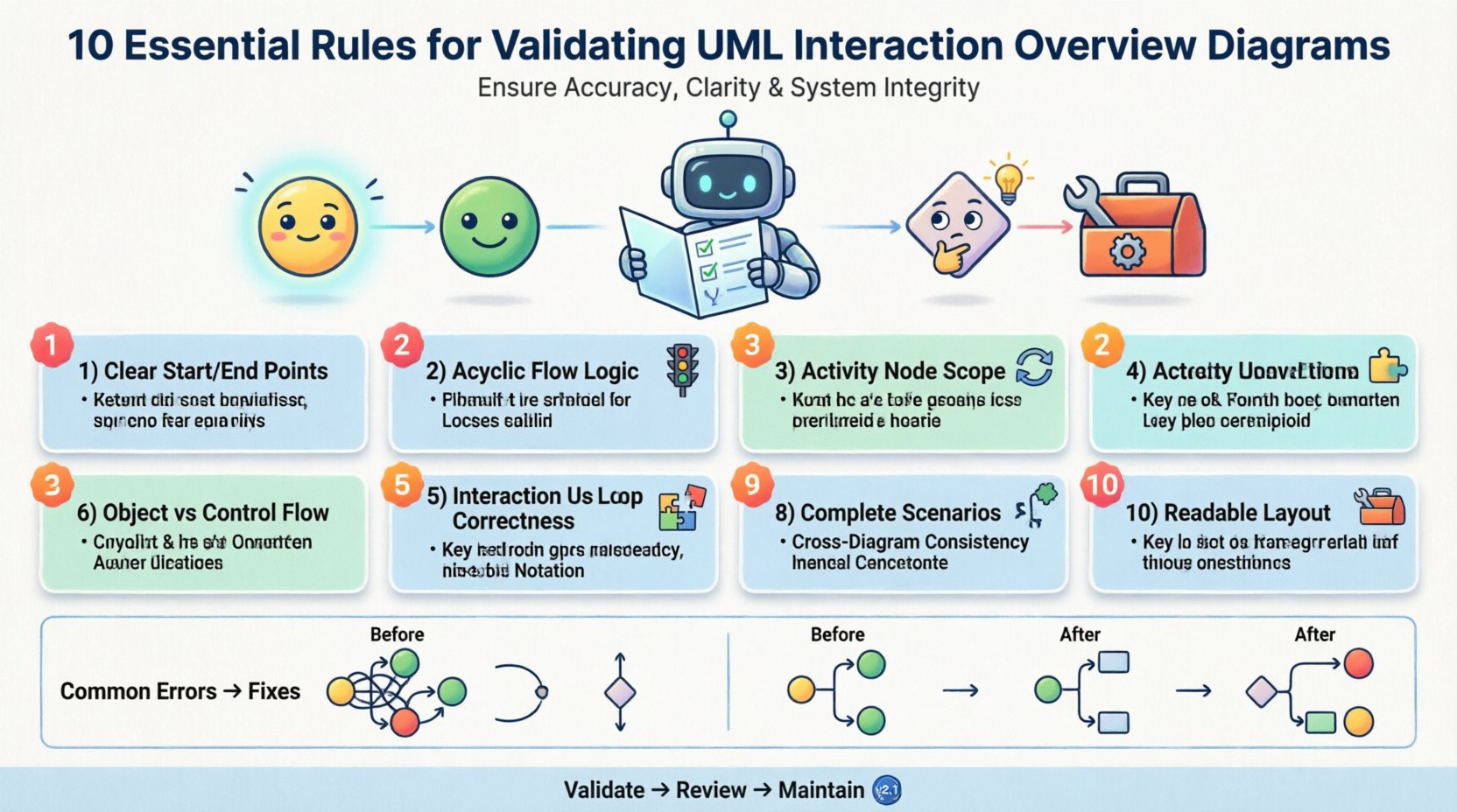
1. Rule: Define Clear Start and End Points 🚦
Every Interaction Overview Diagram must have a distinct entry and exit. Without a defined start node, the origin of the control flow is ambiguous. Similarly, without end nodes, the lifecycle of the interaction is unclear.
- Requirement: Ensure exactly one initial node (filled circle) is present.
- Requirement: Ensure all paths converge to at least one final node (circle with a dot).
- Impact of Violation: Developers may not know where to initialize the process or how to terminate it cleanly.
When validating, trace every line from the start. If a path leads to a dead end without a final node, the diagram is incomplete. Multiple final nodes are acceptable if they represent distinct outcomes (e.g., Success vs. Failure), but they must be clearly labeled.
2. Rule: Ensure Control Flow Logic is Acyclic Where Appropriate 🔁
Control flow nodes dictate the order of execution. Loops are necessary for iteration, but uncontrolled loops or circular dependencies can create infinite execution states that the system cannot handle.
- Requirement: Verify that all loops have a defined exit condition.
- Requirement: Check that conditional branches (decision nodes) do not create unreachable code.
- Impact of Violation: Infinite loops in logic design often translate to infinite loops in code, causing system hangs or crashes.
Review the guard conditions on edges leaving decision nodes. Ensure that the sum of all conditions covers all possibilities, or explicitly define a default path (else). This prevents scenarios where the control flow gets stuck.
3. Rule: Clarify Activity Node Scope and Content 🧩
Activity nodes represent a specific computation or interaction. In an Interaction Overview Diagram, these nodes often encapsulate entire Sequence or Communication diagrams. The scope of these nested interactions must be clear.
- Requirement: Each activity node should represent a single, cohesive logical step.
- Requirement: Avoid nesting too many layers of interaction diagrams within a single node.
- Impact of Violation: Overly complex activity nodes obscure the high-level flow, making the diagram difficult to read and debug.
When validating, ask if the activity node can be represented as a simple sequence of steps. If it requires a separate diagram to explain, ensure that the reference is clear. The IOD should remain a top-level view, not a dumping ground for detailed logic.
4. Rule: Distinguish Object Flow from Control Flow 📦
This is a common source of confusion. Control flow dictates when things happen. Object flow dictates what data is passed between objects. These two flows must not be conflated.
- Requirement: Use solid lines with arrows for control flow (execution order).
- Requirement: Use dashed lines with arrows for object flow (data transfer).
- Impact of Violation: Confusing the two leads to misinterpretation of dependencies. A developer might think data is required for execution when it is actually just a result.
Validate that object flows only enter and exit activity nodes, not decision or fork nodes directly, unless the data influences the logic. Ensure that the objects being passed exist in the system’s class diagram. Mismatched object types indicate a fundamental design flaw.
5. Rule: Validate Interaction Use Correctness 🧪
Interaction Overview Diagrams often reference other interaction diagrams. This creates a dependency chain. The usage must be syntactically and semantically correct.
- Requirement: Ensure the referenced interaction diagram matches the context (e.g., user vs. system).
- Requirement: Verify that the input and output parameters of the referenced interaction match the calling activity.
- Impact of Violation: Mismatched parameters cause runtime errors. Incorrect context leads to logical errors where a subsystem is accessed by the wrong layer.
Check the signature of the interaction. If an activity node calls a sub-process, the data flow entering the sub-process must align with the data flow exiting it. If the sub-process is a sequence diagram, ensure the lifelines involved are consistent with the main diagram’s context.
6. Rule: Apply Consistent Loop and Condition Notation 🔢
Loops and conditions should be denoted using standard UML notation to ensure universal understanding. Informal descriptions in the diagram can lead to varied interpretations among team members.
- Requirement: Use the
{loop}or{while}guard notation clearly. - Requirement: Label all decision nodes with boolean expressions (e.g.,
isValid = true). - Impact of Violation: Ambiguous notation requires manual clarification, slowing down development and increasing the risk of misinterpretation.
Standardize the syntax used for guards. If one section uses if and another uses while, ensure the semantic meaning is identical. Consistency reduces cognitive load for anyone reviewing the architecture.
7. Rule: Enforce Naming Conventions 🏷️
Naming is the interface between the model and the code. Inconsistent naming conventions create a disconnect between the design and the implementation.
- Requirement: Activity names should be verb phrases (e.g.,
Validate Input, notInput Validation). - Requirement: Node names should be unique within the scope of the diagram.
- Impact of Violation: Duplicate names can confuse automated tools and human reviewers. Non-verb activity names can imply nouns, suggesting state rather than action.
Review the text labels on all nodes and edges. Ensure they follow the project’s style guide. Consistent naming makes the diagram self-documenting, reducing the need for external documentation.
8. Rule: Ensure Completeness of Scenarios 🧩
A diagram is only useful if it covers the necessary scenarios. Validation requires checking that edge cases and error paths are not omitted.
- Requirement: Include paths for successful execution and known failure modes.
- Requirement: Verify that alternative flows are explicitly modeled, not just described in text.
- Impact of Violation: Missing error paths lead to unhandled exceptions in production. The system may crash when encountering unexpected input.
Walk through the diagram as if you are an execution engine. Can you reach the end node from the start node in every logical case? If a branch is labeled Failure, ensure it leads to a recovery node or a final error state.
9. Rule: Maintain Consistency with Other Diagrams 🤝
The Interaction Overview Diagram does not exist in isolation. It must align with Class Diagrams, State Machine Diagrams, and Component Diagrams.
- Requirement: Ensure all classes referenced in object flows exist in the Class Diagram.
- Requirement: Ensure states referenced in activity nodes match the State Machine Diagram.
- Impact of Violation: Inconsistency creates silos in the architecture. Developers may implement features that contradict the design, leading to technical debt.
Perform a cross-diagram audit. If an IOD shows an object being passed, verify that the Class Diagram defines that object. If an IOD shows a state transition, verify the State Machine Diagram supports that transition. This alignment is crucial for system coherence.
10. Rule: Optimize Readability and Layout 🎨
Complexity in logic should not result in complexity in visual layout. A diagram that is hard to read is a diagram that will be ignored.
- Requirement: Minimize edge crossings.
- Requirement: Group related activities together spatially.
- Requirement: Use sufficient whitespace to separate distinct logical blocks.
- Impact of Violation: Visual clutter obscures the control flow. Engineers may miss critical connections due to the density of lines.
Layout is not just aesthetic; it is functional. A well-spaced diagram allows the eye to follow the control flow without getting lost. If the diagram is too large, consider splitting it into sub-diagrams based on functional domains.
📊 Common Validation Errors vs. Corrections
The following table summarizes frequent errors encountered during the validation phase and the recommended corrective actions. This serves as a quick reference for reviewers.
| Category | Common Error | Corrective Action |
|---|---|---|
| Flow Logic | Dead-end path without final node | Connect to a final node or add a decision to route flow |
| Data | Object flow entering a decision node | Move object flow to an activity node; use guard for decision |
| References | Missing reference to nested interaction | Add <<include>> or <<extend>> stereotype |
| Notation | Inconsistent loop guard syntax | Standardize on UML guard notation (e.g., {while x}) |
| Completeness | No error handling path | Add exception handling activity and flow to error state |
| Consistency | Class used in IOD not in Class Diagram | Update Class Diagram to include the missing class |
| Layout | Crossing control lines | Reposition nodes to minimize line intersections |
🔄 Maintaining Diagram Consistency Over Time
Validation is not a one-time event. As the system evolves, the Interaction Overview Diagram must evolve with it. Code refactoring, new feature additions, and architectural shifts can all render a previously valid diagram obsolete.
To maintain integrity, implement the following practices:
- Version Control: Store diagrams in the same repository as the source code. Tag diagrams with release versions.
- Change Impact Analysis: Before modifying a class or method, check if the IOD needs updating. If the logic changes, the flow must change.
- Automated Checks: Use static analysis tools to verify that the model matches the code structure where possible.
- Periodic Reviews: Schedule quarterly reviews of the architectural diagrams to ensure they still reflect the current system state.
Keeping diagrams current prevents the “documentation debt” that often plagues software projects. When the diagram matches the code, the documentation becomes a reliable source of truth rather than a historical artifact.
🛠 Integrating Validation into Your Workflow
Incorporating these rules into your development workflow requires discipline but yields significant returns in quality. Here is a suggested process for integrating validation:
- Self-Check: After drawing the diagram, run through the 10 rules checklist before sharing.
- Peer Review: Have a colleague review the diagram specifically for logical gaps. Fresh eyes catch issues the author misses.
- Code Walkthrough: During code review, compare the implementation against the IOD. Discrepancies should be noted and resolved.
- Test Coverage: Use the IOD to generate test scenarios. If a path in the diagram is not tested, the diagram may be too complex or the test coverage is insufficient.
By treating the diagram as a living document subject to the same quality standards as code, you ensure that the design remains robust. This approach aligns with best practices in model-driven development and system engineering.
📝 Final Thoughts on Diagram Validation
Validating an Interaction Overview Diagram is about precision and clarity. It ensures that the intended behavior of the system is accurately captured before implementation begins. Following these ten rules helps eliminate ambiguity, reduces technical debt, and facilitates smoother communication across the team. A well-validated diagram is a foundation for reliable software.
Remember that the goal is not perfection in the first draft, but a structured approach to improvement. Apply these rules iteratively, refine your models, and maintain a strict link between your design and your code. This discipline elevates the quality of the entire software delivery process.

