


Designing a robust system requires more than just functional requirements; it demands a clear visualization of how data and actors move through a network. An Interaction Overview Diagram serves as the blueprint for these movements, capturing the high-level logic before diving into specific class or sequence details. This guide provides a deep dive into constructing these flows with precision, ensuring clarity for developers, stakeholders, and maintainers alike.
Complexity often arises not from the number of steps, but from the branching logic and the state dependencies between them. When mapping these interactions, the goal is to reduce ambiguity. This process involves identifying actors, defining entry points, establishing decision nodes, and handling exception paths. By following a structured methodology, you can create diagrams that communicate intent effectively.
1. Understanding the Foundation 🧱
Before drawing a single line, it is crucial to understand what the diagram represents. An Interaction Overview Diagram is not a sequence diagram. While a sequence diagram focuses on the order of messages between objects in a specific scenario, an overview diagram focuses on the control flow between activity nodes. It is a hybrid that combines aspects of activity diagrams with the flow control of a flowchart.
When beginning this construction process, consider the following principles:
- High-Level Abstraction: Do not get bogged down in method signatures or variable names. Focus on the logical progression.
- Actor Identification: Clearly define who or what initiates the process. Is it a human user, an external API, or an internal scheduler?
- Goal Orientation: Every flow must have a defined start and a successful end state. Ambiguity in termination points leads to implementation errors.
Starting with a clear scope prevents the diagram from becoming a tangled web. Define the boundary conditions early. What is included in this specific interaction? What is handled by another system or module? Keeping the scope tight ensures the diagram remains readable.
2. Preparing the Data and Entities 📋
Construction begins with the inventory. You cannot map a flow without knowing the components involved. This phase is about gathering the necessary artifacts to populate the diagram accurately.
- Identify Actors: List every entity capable of initiating or receiving an action. Use distinct icons or labels to differentiate between human users, automated services, and database systems.
- Define Data Objects: What information is passed between nodes? A payment record, a user session token, or a status update. Naming these objects consistently is vital for downstream documentation.
- Map Dependencies: Determine which processes rely on the output of others. This establishes the directionality of the arrows connecting your nodes.
It is common to overlook external dependencies during this phase. Ensure that any third-party service calls are represented as distinct nodes. If a service fails, the flow must account for that reality. Do not assume ideal conditions.
3. The Construction Steps 🛠️
The actual drawing process follows a logical sequence. Attempting to draw randomly often leads to crossing lines and confusion. Follow this step-by-step approach to build a clean, maintainable diagram.
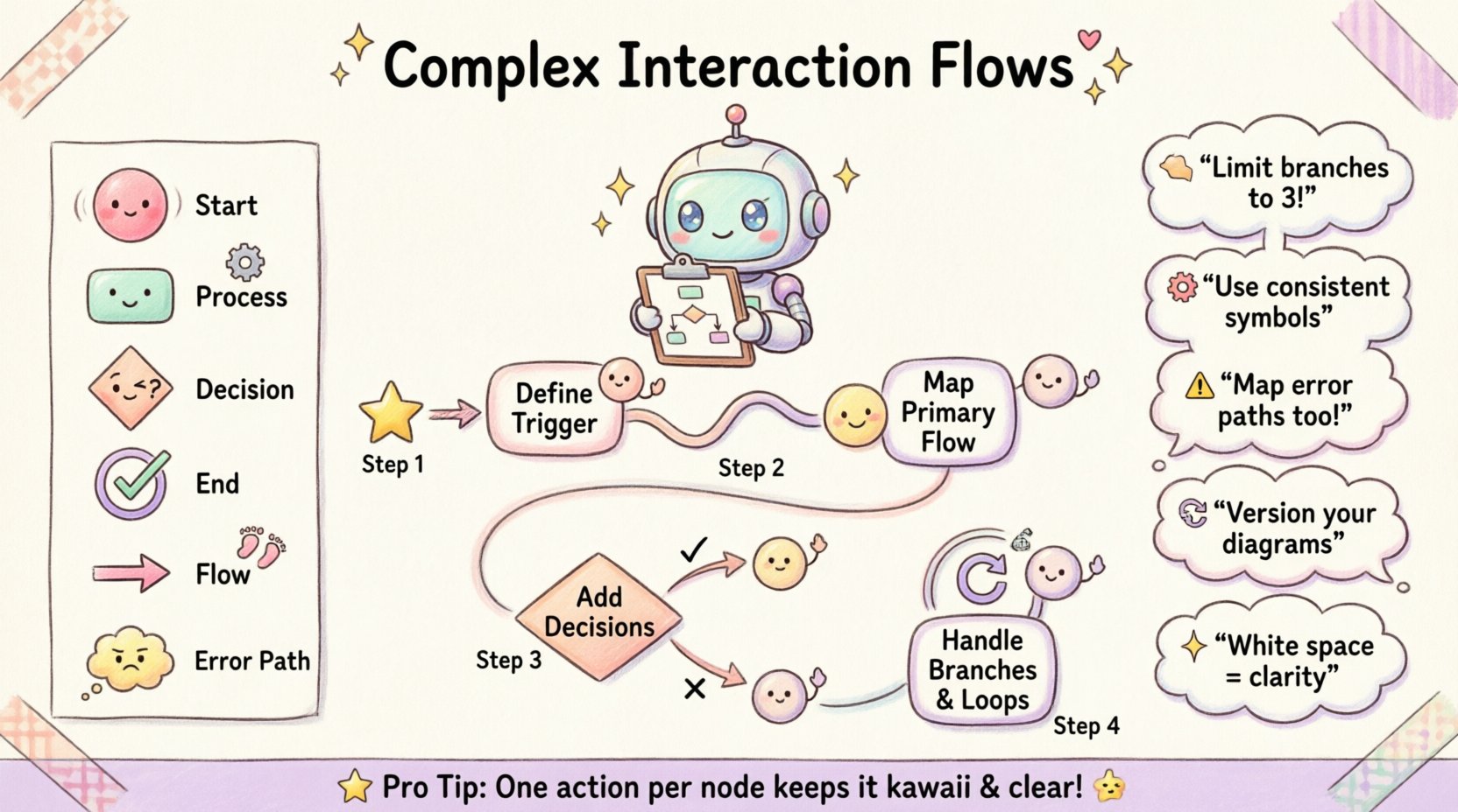
Step 1: Define the Entry Point
Start with the trigger. This is the event that initiates the interaction. It could be a user clicking a button, a webhook receiving a payload, or a scheduled cron job. Represent this clearly at the top or left of the canvas. Use a filled circle to denote the initial state.
Step 2: Map the Primary Path
Draw the happy path first. This is the sequence of actions that occurs when everything proceeds as expected. Connect the entry point to the first processing node. Continue this chain until you reach the completion state. This establishes the baseline for the system.
- Ensure every node on the primary path represents a distinct action or decision.
- Label the edges connecting these nodes with the specific condition or data transfer.
- Avoid placing multiple actions in a single box. One action per node improves readability.
Step 3: Introduce Decision Points
Real-world systems rarely follow a single straight line. Introduce decision diamonds where the flow splits based on conditions. These nodes typically have two or more outgoing edges, each labeled with a boolean outcome (e.g., “True”/”False” or “Success”/”Failure”).
When placing decision points, ensure they are placed logically. Do not cluster too many decisions in one area. Spread them out to allow for clear routing of the paths.
Step 4: Handle Branching and Loops
Complex interactions often involve loops. A user might retry an action, or a process might iterate over a list of items. Represent loops by drawing an arrow that returns to a previous node. Label this edge clearly with the condition for looping back.
Be cautious with infinite loops. Ensure every loop has a defined exit condition. If a process is designed to run indefinitely, document the termination criteria elsewhere. For finite loops, specify the maximum iteration count if applicable.
4. Visual Standards and Symbols 🎨
To ensure that anyone reading the diagram understands it immediately, adhere to a consistent set of visual standards. Using a standard legend helps reduce the cognitive load for the reader.
| Symbol | Meaning | Usage Context |
|---|---|---|
| 🔴 Filled Circle | Start Node | Represents the entry point of the interaction flow. |
| ⬜ Rounded Rectangle | Activity / Process | Represents a specific action or task being performed. |
| 🔶 Diamond | Decision Point | Represents a branching path based on a condition. |
| 🔵 Double Circle | End Node | Represents the successful completion or termination of the flow. |
| 🔵 Single Circle | Initial State | Can be used to denote the initial state before the start node in complex state transitions. |
| ➡️ Arrow | Control Flow | Indicates the direction of the process flow between nodes. |
| ⚠️ Exclamation Icon | Exception / Error | Highlights paths taken when an error or unexpected condition occurs. |
Consistency in these symbols is non-negotiable. If you decide to use a diamond for decisions, do not switch to a hexagon for the same purpose later in the document. This consistency allows team members to scan the diagram quickly.
5. Handling Exceptions and Error States ⚠️
A diagram is only as good as its ability to represent reality. Reality includes failures. Ignoring error states creates a false sense of security. You must explicitly map what happens when a step fails.
- Identify Failure Points: For every external call or data write, identify the potential failure mode. Does the network timeout? Is the data invalid? Is the user unauthorized?
- Define Recovery Paths: For each failure, define the recovery. Do you retry? Do you notify an admin? Do you abort the transaction?
- Log and Monitor: Every error path should imply a logging action. This ensures that the system behavior is auditable.
Do not merge all error paths into a single “Fail” node unless the handling logic is identical. Specific errors often require specific responses. A database connection error is handled differently than a validation error. Keep these paths distinct.
6. Validation and Refinement 🔍
Once the initial construction is complete, the diagram must undergo a rigorous review. This phase ensures that the logic holds up under scrutiny and that the visual representation matches the intended design.
Peer Review Process
Have a colleague who was not involved in the creation review the diagram. Their fresh perspective is invaluable. Ask them specific questions:
- Can you trace the flow from start to finish without confusion?
- Are there any paths that seem dead-ended?
- Is the distinction between success and failure clear?
Gap Analysis
Compare the diagram against the functional requirements document. Check for missing steps. If the requirements mention a notification step that is absent from the diagram, add it. Conversely, if the diagram includes steps not in the requirements, verify if they are necessary.
Scalability Check
Consider how this diagram will look in six months. Will adding new features require a complete redraw? Try to design the nodes to be modular. If a process is complex, consider breaking it into a sub-flow or a separate diagram. This keeps the main overview clean.
7. Cognitive Load Management 🧠
The most technically accurate diagram is useless if no one can read it. Managing cognitive load is a critical aspect of the design process. Humans have limited working memory. Overloading a single view leads to errors.
- Limit Branching: Try to avoid more than three outgoing edges from a single decision node. If you have more, consider grouping them or creating a sub-diagram.
- Use White Space: Do not cram nodes together. Allow breathing room between elements. This helps the eye follow the path naturally.
- Group Related Logic: Use swimlanes or containers to group actions that belong to the same actor or subsystem. This visual grouping aids in understanding ownership.
Color can be a helpful tool, but use it sparingly. Reserve color for highlighting critical paths, exceptions, or warning states. Avoid using color just for decoration. Stick to a muted palette for standard nodes and bright colors only for emphasis.
8. Maintenance and Versioning 🔄
Software evolves. The interaction flows must evolve with it. A static diagram becomes a liability if it does not reflect the current system state. Establish a versioning strategy for your diagrams.
- Version Control: Store diagram files in the same repository as the code. Tag versions to match code releases.
- Change Logs: Maintain a log of changes made to the interaction flows. Note why a change was made and who approved it.
- Review Cadence: Schedule periodic reviews of the diagrams. Ensure they remain relevant as features are deprecated or added.
When updating a diagram, ensure all downstream documentation is updated as well. Sequence diagrams, API documentation, and user guides often reference the interaction overview. Consistency across documentation is key.
9. Common Pitfalls to Avoid 🚫
Even experienced designers make mistakes. Being aware of common pitfalls helps you steer clear of them.
- Leveling Confusion: Do not mix high-level logic with low-level implementation details in the same view. Keep the overview high-level.
- Missing Termination: Ensure every path eventually leads to a stop. Avoid paths that just disappear.
- Over-Complexity: If a flow becomes too complex, break it down. It is better to have three simple diagrams than one massive, unreadable one.
- Ignoring Context: Do not assume the reader knows the context. Label inputs and outputs clearly.
10. Final Considerations for Clarity 🌟
Creating a complex interaction flow is an exercise in communication. It is about translating abstract logic into a visual language that a team can understand and execute. The effort spent on precision now saves countless hours of debugging and confusion later.
Remember that the diagram is a living document. It should be treated with the same care as the code it describes. Regular updates and adherence to visual standards ensure that the knowledge remains accessible. By following these steps, you establish a solid foundation for system design that supports scalability and maintainability.
Focus on the logic, not the aesthetics alone. A clean diagram that accurately represents the flow is superior to a pretty one that obscures the truth. Use the tools available to you to ensure clarity, but rely on principles of design to guide the structure. With a methodical approach, you can construct interaction flows that serve as reliable guides for your entire development lifecycle.

