
Mastering Order Lifecycle State Machines with UML and VPasCode
In modern software architecture, the lifecycle of an entity—such as an Order, a Ticket, or a User Account—is rarely linear. It is a complex web of conditions, events, and state changes. This tutorial demonstrates how to effectively model these lifecycle-heavy entities using State Machines. We will utilize VPasCode, Visual Paradigm’s Diagram-as-Code tool, to bridge the gap between text-based logic and visual system architecture.
Why Use State Machines for Complex Entities?
When you are building an application where behavior depends heavily on the current status of an object, a simple flowchart is often insufficient. A State Machine is the architectural pattern of choice when:
- Behavior is State-Dependent: The actions available to a user or system change based on the current state (e.g., you can “Cancel” an order only if it is “Pending” or “Confirmed”).
- Invalid Transitions Must Be Prevented: You need to ensure that data integrity is maintained (e.g., an order cannot go from “Shipped” directly to “Draft”).
- Event-Driven Logic: The system reacts to external triggers (like “payment approved” or “dispatch”) to move between states.
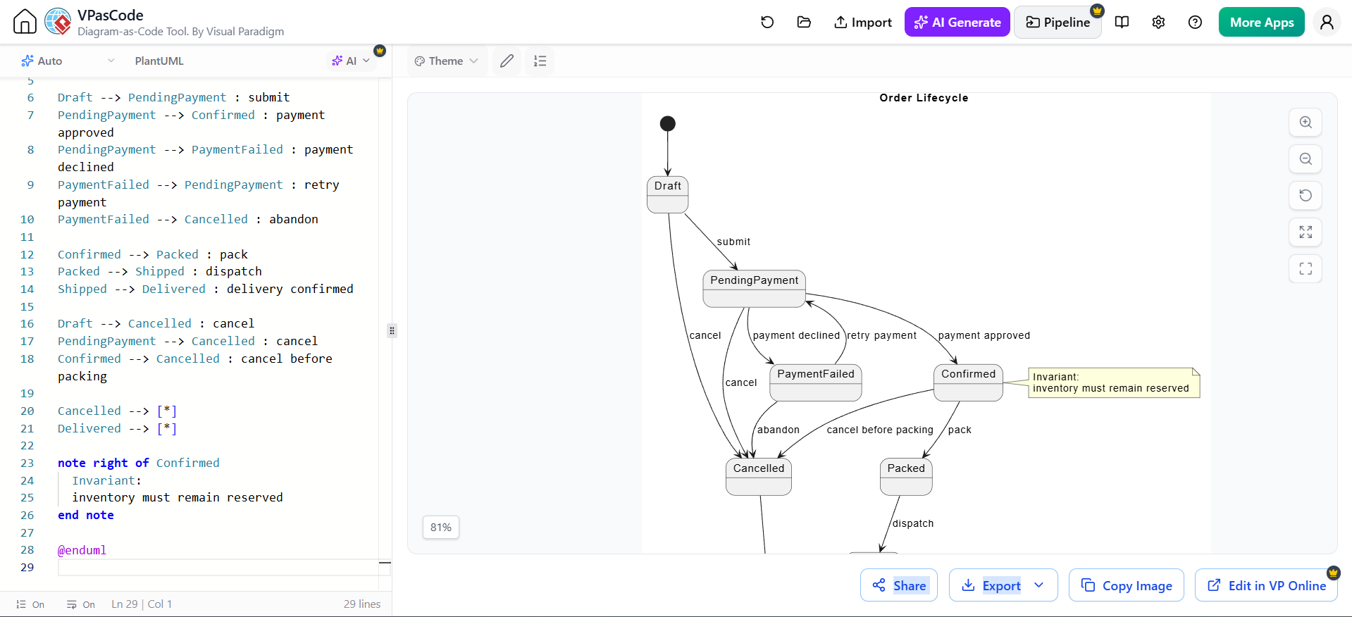
The diagram shown in the context represents an Order Lifecycle. It visualizes the journey of an order from its initial creation to final delivery or cancellation.
Step-by-Step: Modeling with VPasCode
VPasCode allows you to write code that automatically generates diagrams. This approach is superior to drag-and-drop tools for complex systems because it enforces consistency and makes version control of your architecture possible.
1. Defining the States
Every state machine begins with its states. In the code below, we see the core states of our Order entity:
Draft: The order has been created but not submitted.PendingPayment: The order is submitted, waiting for payment.PaymentFailed: The payment attempt was rejected.Confirmed: Payment was successful.Packed: The item has been prepared for shipping.Shipped&Delivered: The physical fulfillment states.Cancelled: The order lifecycle is terminated.
2. Modeling Transitions (The Logic)
The transitions define how the system moves from one state to another. In VPasCode, this is written using the syntax StateA --> StateB : Event.
Example: The Payment Flow
Consider the logic for an order that has been submitted:
Draft --> PendingPayment : submit
PendingPayment --> Confirmed : payment approved
PendingPayment --> PaymentFailed : payment declined
PaymentFailed --> PendingPayment : retry payment
PaymentFailed --> Cancelled : abandon
This block of code establishes that:
- A
DraftbecomesPendingPaymentuponsubmit. - If
payment approved, it moves toConfirmed. - If
payment declined, it moves toPaymentFailed. - Crucially, from
PaymentFailed, the system allows two paths: aretry payment(looping back) or anabandon(moving to Cancelled).
3. Handling Side-Effects and Guards
Real-world business logic often includes “cancellation” paths that are available at multiple stages. The code handles this efficiently by defining the transition from the source state:
Draft --> Cancelled : cancel
PendingPayment --> Cancelled : cancel
Confirmed --> Cancelled : cancel before packing
Notice the specificity in the label cancel before packing. This semantic detail is vital for understanding the business rule: once an order is packed, the cancellation process changes (perhaps requiring a return process instead of a direct cancel).
4. Adding Invariants and Documentation
State machines are not just about movement; they are about rules. In the diagram, there is a constraint attached to the Confirmed state. In the code, this is defined using a note block:
note right of Confirmed
    Invariant:
    inventory must remain reserved
end note
This Invariant is a critical architectural constraint. It tells the developer that while the order is in the Confirmed state, the system must ensure that the inventory for that item is locked and cannot be sold to another customer. This prevents overselling.
From Code to Visual Architecture
When you run this code in VPasCode, the engine parses the syntax and renders the diagram. You will see a visual representation that matches the logic perfectly:
- Nodes: The states are rendered as rounded rectangles.
- Edges: The arrows represent the transitions, labeled with the triggering event.
- Annotations: The yellow note box appears next to the
Confirmedstate, visually highlighting the inventory constraint.
This visual output is not just for documentation; it serves as a “Single Source of Truth” for backend developers, frontend UI designers (who need to know which buttons to show based on state), and QA testers (who can verify all transition paths).
Conclusion
By using VPasCode to model the Order Lifecycle, you ensure that your system architecture is robust, documented, and logically consistent. The separation of logic (code) and presentation (diagram) allows for easier maintenance of lifecycle-heavy entities, ensuring that your software behaves predictably under all circumstances.