
Mastering System Requirements with VPasCode: Online Store Use Case Diagrams
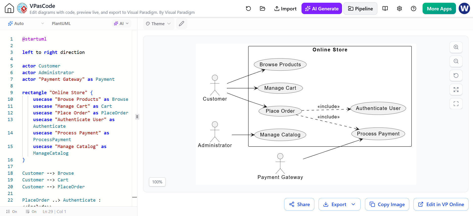
In the realm of software engineering, visualizing how users interact with a system is crucial before writing a single line of functional code. This tutorial explores the creation of a Use Case Diagram for an “Online Store” system. We will deconstruct the provided PlantUML code to understand how actors, boundaries, and relationships are modeled to define the system’s scope.
Understanding the Core Components
A Use Case Diagram is a dynamic diagram that illustrates the functional requirements of a system. It answers the question: “Who can do what within this system?”
1. The Actors (Who)
Actors represent the external entities interacting with the system. In our example, we have three distinct actors:
- Customer: The primary user who browses, shops, and purchases items.
- Administrator: The internal user responsible for managing the store’s inventory.
- Payment Gateway: An external system actor. This is a critical distinction; it shows that the system relies on an external service to complete transactions.
2. The System Boundary (Where)
The rectangle "Online Store" defines the scope of our application. Everything inside this box represents functionality provided by the system. Anything outside is an external actor.
3. The Use Cases (What)
Use cases are the specific goals or actions the actors can perform:
- Browse Products: Viewing the catalog.
- Manage Cart: Adding or removing items.
- Place Order: Finalizing a purchase.
- Authenticate User: Logging in (a security requirement).
- Manage Catalog: The Admin’s ability to update products.
Analyzing the Relationships
The power of a Use Case Diagram lies in connecting actors to use cases. The code utilizes specific arrows to define these interactions.
1. Association (Solid Lines)
These represent a direct communication path. For example, the Customer interacts directly with the “Browse Products” and “Manage Cart” functions.
2. Inclusion (Dashed Lines with «include»)
This is a vital modeling concept. The diagram shows that Place Order includes Authenticate User and Process Payment. This means that “Place Order” is a complex action that cannot happen without these specific sub-steps occurring first. It enforces business rules visually.
Deep Dive: The PlantUML Syntax
The diagram is generated using PlantUML, a text-based diagramming tool. Let’s break down the logic used in the code snippet to see how text translates to visuals.
@startuml
left to right direction

actor Customer
actor Administrator
actor "Payment Gateway" as Payment

rectangle "Online Store" {
    usecase "Browse Products" as Browse
    usecase "Manage Cart" as Cart
    usecase "Place Order" as PlaceOrder
    usecase "Authenticate User" as Authenticate
    usecase "Process Payment" as ProcessPayment
    usecase "Manage Catalog" as ManageCatalog
}

Customer --> Browse
Customer --> Cart
Customer --> PlaceOrder

PlaceOrder ..> Authenticate : <>
PlaceOrder ..> ProcessPayment : <>

Administrator --> ManageCatalog
Payment --> ProcessPayment
@enduml
Notice the rectangle block. This creates the system boundary. Inside, we define the usecase elements and assign them aliases (e.g., as Browse) to make the connection lines cleaner.
The connection lines use specific syntax:
-->creates a standard solid arrow (Association)...>creates a dashed arrow (Dependency).: «include»adds the specific stereotype text to the dashed line, visually explaining the mandatory dependency.
Conclusion
By translating the text-based PlantUML code into a visual diagram, we gain an immediate understanding of the Online Store’s architecture. We can see that the Customer is the primary driver of revenue, while the Administrator maintains the inventory. Crucially, the diagram highlights the dependencies: you cannot place an order without authenticating and processing payment. This visual clarity is essential for developers to build robust, requirement-compliant software.