
Mastering Visual Paradigm UML Package Diagrams for Scalable Architecture
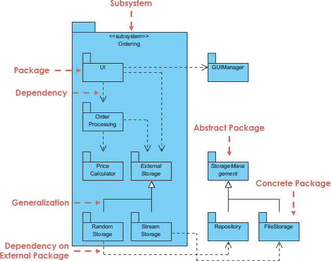
In the realm of complex software engineering, managing the sheer volume of classes and components can become overwhelming. This is where the Package Diagram becomes an indispensable tool for architects and developers. Unlike a Class Diagram, which dives deep into the specifics of individual objects, a Package Diagram provides a high-level map of your system, organizing model elements into groups to manage complexity, namespaces, and dependencies.
This tutorial will guide you through the core concepts of Package Diagrams, the specific architectural elements visible in our system overview, and how leveraging the Visual Paradigm ecosystem can streamline your modeling workflow.
Understanding the Core Purpose
A Package Diagram is designed for large projects where the relationships between large groups of components are more critical than the internal details of those components. Its primary goals are:
- Namespace Management: Preventing naming conflicts by grouping related classes into distinct scopes.
- Dependency Management: Visualizing how different parts of your system rely on one another, ensuring a clean separation of concerns.
- Logical Grouping: Creating a logical hierarchy that mirrors the physical folder structure of your source code.
Key Architectural Elements Explained
Based on the system architecture diagram provided, we can break down the essential elements that make a Package Diagram effective.
1. The Subsystem and Package Container
The large blue container in the diagram represents a SubSystem named “Ordering”. In modeling terms, a Package acts as a container that holds other packages or classes. It is often visualized as a folder with a small tab.
- UI (User Interface): Located at the top, this package likely holds all classes related to the user interface logic.
- Order Processing: The core business logic package that orchestrates the flow of an order.
2. Dependencies (The Dashed Arrow)
Dependencies indicate a usage relationship. If Package A depends on Package B, changes in B might impact A. In the diagram, notice the dashed arrows originating from UI pointing to GUIManager and Order Processing.
@startuml
package "Ordering System" {
  package "UI" {
    class LoginScreen
  }

  package "Order Processing" {
    class OrderManager
  }

  ' Dependency: UI needs Order Processing
  UI ..> Order Processing
@enduml
3. Generalization (Inheritance)
The solid line with a hollow triangle arrowhead represents Generalization, which is the UML term for inheritance. This is crucial for polymorphism and code reuse.
- Storage Hierarchy: In the lower section of the diagram, we see
Random StorageandStream Storageinheriting from a parent concept (implied by the upward arrows). This allows the system to treat different storage types uniformly.
4. Abstract vs. Concrete Packages
The diagram explicitly distinguishes between Abstract Packages and Concrete Packages.
- Abstract Package (Storage Management): This represents a contract or an interface. It defines what a storage mechanism should do without specifying how it does it.
- Concrete Package (Repository, FileStorage): These are the actual implementations. They inherit from the abstract package and provide the specific logic for storing data in a database or on a file system.
Tooling and Collaboration: The Visual Paradigm Advantage
While understanding the theory is vital, executing it efficiently requires the right tools. Visual Paradigm offers a comprehensive suite of features that integrate seamlessly with standard UML specifications.
Boosting Team Productivity
When modeling complex systems, the ability to switch between different views of your architecture is critical. Visual Paradigm’s core pillars—such as its robust UML modeling engine and collaborative cloud features—ensure that:
- Seamless Integration: You can model the “SubSystem” structure visually and then automatically generate the corresponding folder structure in your IDE (e.g., Eclipse, IntelliJ).
- Real-Time Collaboration: Teams can work on the same Package Diagram simultaneously, ensuring that the
Order Processinglogic remains consistent across the board. - Code Generation: Once the
Abstract PackageandConcrete Packagerelationships are finalized, you can generate the skeleton Java/C# code in seconds.
Usage Cases
Visual Paradigm is particularly powerful when used in the following scenarios:
- Legacy Refactoring: Reverse engineering existing codebases into Package Diagrams to understand dependencies before refactoring.
- Microservices Architecture: Defining boundaries between microservices using packages, where each package represents a deployable service.
Conclusion
By mastering the Package Diagram, you gain the ability to navigate and design large-scale systems with clarity. Whether you are defining the Generalization hierarchy for storage solutions or managing the Dependencies between your UI and backend, these diagrams provide the blueprint for success. With tools like Visual Paradigm, these complex models become living documents that drive your team’s productivity and code quality.