
Architecting Smart Cities: A Step-by-Step Guide to Modeling Traffic Management Systems with ArchiMate and PlantUML
In the rapidly evolving landscape of modern urbanization, cities face unprecedented challenges in managing traffic congestion, reducing emissions, and improving citizen mobility. Traditional traffic management systems, often reliant on static timing schedules and manual monitoring, struggle to keep pace with the dynamic nature of modern transportation demands. The emergence of smart city technologies—combining Internet of Things (IoT) sensors, artificial intelligence, cloud computing, and real-time data analytics—offers a transformative solution to these persistent problems.
However, implementing such complex systems requires more than just selecting the right technologies; it demands a clear architectural vision that aligns business objectives with technical capabilities. This is where enterprise architecture frameworks like ArchiMate become invaluable. ArchiMate provides a standardized visual language for describing, analyzing, and communicating the relationships between business processes, application services, and technology infrastructure.
This comprehensive tutorial demonstrates how to model a Smart City Traffic Management System using ArchiMate notation through PlantUML code. We will explore a realistic problem scenario faced by the City of San Francisco, create a comprehensive three-layer architecture diagram, and provide detailed interpretation of the architectural decisions.
1. The Problem Scenario: San Francisco Traffic Optimization
To ground our architectural modeling in reality, we define the scope of the system. The City of San Francisco is implementing a Smart Traffic Management System designed to reduce congestion and improve traffic flow across the city. The system must satisfy several critical functional requirements:
- Data Ingestion: Collect real-time traffic data from IoT sensors installed at major intersections.
- Intelligent Processing: Process and analyze traffic patterns using AI algorithms.
- Dynamic Control: Provide dynamic traffic light optimization based on current conditions.
- Citizen Engagement: Offer citizens real-time traffic information through a mobile application.
- Operational Oversight: Enable traffic management officials to monitor and control the system through a dashboard.
- Integration: Integrate with existing public transportation systems (buses, trains).
Key Stakeholders driving this system include Citizens/Commuters, Traffic Management Officials, the City Planning Department, and the IT Operations team. The architecture must ensure high-volume data processing, real-time responsiveness, and robust security.
2. Understanding the Three-Layer Architecture
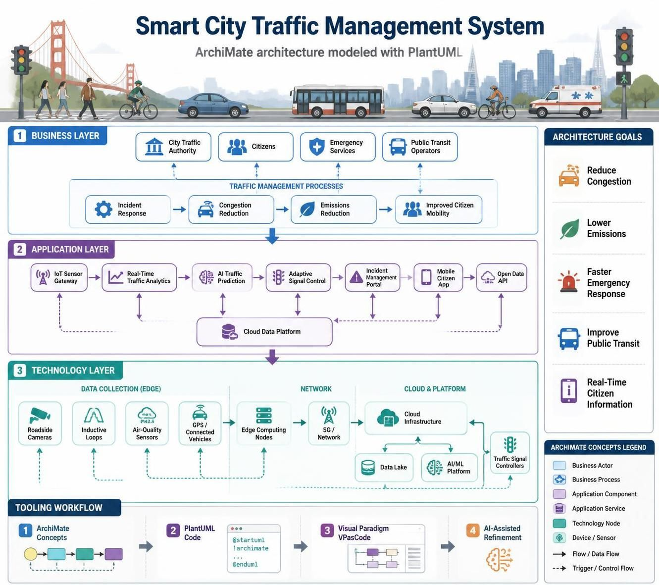
ArchiMate organizes architecture into three distinct but interconnected layers: Business, Application, and Technology. In our Smart City model, these layers map the “Why,” “What,” and “How” of the solution.
Layer 1: The Business Layer
The Business Layer defines the strategic objectives and processes. It connects stakeholders to business goals. In our diagram, we model:
- Business Actors: The City Traffic Authority, Citizens, Emergency Services, and Public Transit Operators.
- Business Processes: Incident Response, Congestion Reduction, Emissions Reduction, and Improved Citizen Mobility.
- Architecture Goals: These are the high-level outcomes the system must achieve, such as “Reduce Congestion” and “Lower Emissions.”
Layer 2: The Application Layer
The Application Layer describes the software services and components required to support the business processes. It acts as the bridge between business needs and technical infrastructure. Our model includes:
- IoT Sensor Gateway: The entry point for raw data.
- Real-Time Traffic Analytics: The processing engine for pattern recognition.
- Adaptive Signal Control: The logic that determines traffic light timings.
- Cloud Data Platform: The central repository (Data Lake) storing historical and real-time data.
Layer 3: The Technology Layer
The Technology Layer represents the physical hardware and software that executes the application services. This is the physical reality of the smart city. We model:
- Data Collection (Edge): Roadside cameras, inductive loops, air-quality sensors, and GPS/Connected Vehicles.
- Network: 5G and network infrastructure connecting edge devices to the cloud.
- Cloud Infrastructure: The servers hosting the AI/ML platforms and data lakes.
- Traffic Signal Controllers: The physical actuators that change traffic lights.
3. Modeling the System with PlantUML and VPasCode
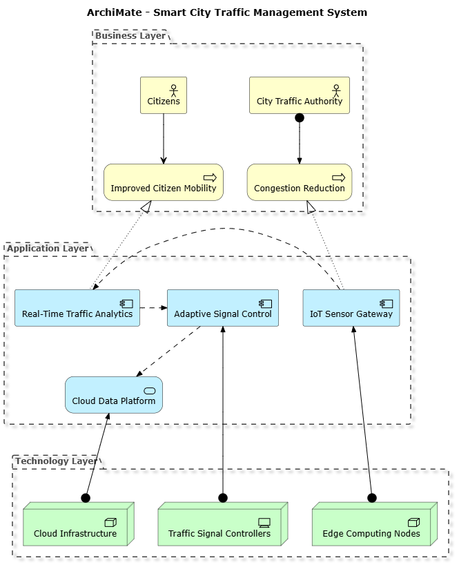
To visualize this architecture, we utilize the VPasCode plugin for Visual Paradigm, which allows architects to write ArchiMate diagrams using PlantUML syntax. This approach streamlines the design process and allows for version control of architecture.
The following code snippet demonstrates how to define the core components of the Smart City Traffic Management System using ArchiMate stereotypes.
@startuml
!include https://static.visual-paradigm.com/plantuml-stdlib/Archimate-PlantUML/master/Archimate.puml

title ArchiMate - Smart City Traffic Management System

Grouping(business_layer, "Business Layer") {
  Business_Actor(citya, "City Traffic Authority")
  Business_Actor(citizens, "Citizens")
  Business_Process(congred, "Congestion Reduction")
  Business_Process(mobimp, "Improved Citizen Mobility")
}

Grouping(application_layer, "Application Layer") {
  Application_Component(iotgw, "IoT Sensor Gateway")
  Application_Component(rta, "Real-Time Traffic Analytics")
  Application_Component(sigctrl, "Adaptive Signal Control")
  Application_Service(clouddb, "Cloud Data Platform")
}

Grouping(technology_layer, "Technology Layer") {
  Technology_Node(edge, "Edge Computing Nodes")
  Technology_Node(cloudinfra, "Cloud Infrastructure")
  Technology_Device(sigdev, "Traffic Signal Controllers")
}

' Business actors drive / benefit from the business processes
Rel_Assignment(citya, congred, "")
Rel_Serving(citizens, mobimp, "")

' Business processes are realized by the application layer
Rel_Realization_Up(iotgw, congred, "")
Rel_Realization_Up(rta, mobimp, "")

' Application flow between system components
Rel_Flow_Right(iotgw, rta, "")
Rel_Flow_Right(rta, sigctrl, "")
Rel_Flow_Down(sigctrl, clouddb, "")

' Technology layer is assigned to support the application layer
Rel_Assignment_Up(edge, iotgw, "")
Rel_Assignment_Up(cloudinfra, clouddb, "")
Rel_Assignment_Up(sigdev, sigctrl, "")

@enduml
4. Interpreting the Architectural Decisions
When analyzing the resulting diagram, several critical architectural decisions become apparent:
- Edge vs. Cloud Computing: The model explicitly separates “Edge Computing Nodes” from the “Cloud Infrastructure.” This is a crucial decision for smart cities. By processing data at the edge (closer to the sensors), the system reduces latency for critical functions like traffic light control. Only aggregated or historical data is sent to the Cloud Data Platform for long-term analysis.
- Real-Time Responsiveness: The direct flow from “AI Traffic Prediction” to “Adaptive Signal Control” ensures that the system reacts instantly to changing conditions, rather than relying on pre-set schedules.
- Integration Strategy: The inclusion of “Public Transit Operators” in the Business Layer and the “Mobile Citizen App” in the Application Layer ensures that the system is not siloed. It connects the infrastructure directly to the users and other transport modes.
5. The Tooling Workflow
Architecting such a complex system is a collaborative effort. The workflow typically follows these steps:
- Conceptualization: Architects identify the key ArchiMate concepts (Actors, Processes, Nodes) needed to solve the problem.
- Textual Modeling: Using VPasCode, architects write the PlantUML code to generate the diagram. This is faster than dragging and dropping shapes and ensures consistency.
- AI-Assisted Refinement: Modern tools can use AI to suggest missing relationships or identify gaps in the architecture based on the written code.
- Visualization & Review: The generated diagram serves as the single source of truth for stakeholders, bridging the gap between technical implementation and strategic vision.
By following this structured approach, enterprise architects can design smart city solutions that are not only technologically advanced but also aligned with the strategic goals of the municipality.