
Understanding Inheritance Hierarchies in UML Class Diagrams
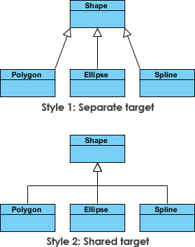
In the realm of object-oriented system design, few concepts are as fundamental or as powerful as inheritance. It serves as the backbone for code reuse, polymorphism, and the creation of maintainable software architectures. Visual Paradigm, a leading tool for software modeling, provides robust support for these concepts, allowing architects to visualize complex relationships with clarity. One of the most common sources of confusion for beginners is the representation of inheritance. As illustrated in the standard “Shapes” example, inheritance can be depicted using different visual styles, yet the underlying semantic meaning remains identical.
This article provides a deep-dive technical analysis of UML inheritance, specifically focusing on the “Shapes” hierarchy example. We will explore the foundational principles, dissect the notation variations, and analyze the core mechanisms that drive this relationship.
The Semantic Equivalence of Notation Styles
When examining the inheritance hierarchy for the “Shapes” domain, one often encounters two distinct visual representations of the same relationship. In the example provided by Visual Paradigm, we see a base class Shape and two subclasses, Circle and Square. While the connectors drawn between these classes may appear different at a glance, they are semantically equivalent.
The first style typically features a solid line ending in a hollow triangle arrowhead pointing toward the superclass. The second style might utilize a specific connector tool or a slightly different alignment, yet the direction and the arrowhead type are the critical factors. In UML, the hollow triangle is the universal symbol for generalization (inheritance). Regardless of whether the line is straight, curved, or routed in a specific way by the modeling tool, the meaning is absolute: the subclass inherits the attributes and operations of the superclass.
Key Insight: In UML, the visual path of the line is a stylistic choice for layout optimization, while the arrowhead type defines the semantic relationship. A solid line with a hollow triangle always denotes “is-a” relationship.
Foundational Principles of the Shapes Hierarchy
To understand why the Shapes example is so prevalent in technical literature, we must analyze the domain logic it represents. The hierarchy is built on the principle of abstraction.
- The Superclass (Shape): This represents the most general concept. It defines the common properties shared by all shapes, such as color, position, or methods like draw(). It serves as the contract that all specific shapes must adhere to.
- The Subclasses (Circle, Square): These represent specialized implementations. A Circle inherits the general properties of a Shape but adds specific attributes like radius. Similarly, a Square inherits the base properties but introduces side_length.
This structure allows developers to write code that operates on the Shape type, treating both Circle and Square objects uniformly. This is the essence of polymorphism, which relies entirely on the inheritance relationship defined in the diagram.
Notation and Symbol Analysis
The UML specification is precise regarding notation. In the context of the Shapes example, the following symbols and rules apply:
The Generalization Arrow
The core symbol is the Generalization connector. It is visually represented by:
- A solid line connecting the subclass to the superclass.
- A hollow (unfilled) triangle at the end of the line pointing to the superclass.
It is crucial to note that the arrow always points toward the superclass. This directionality indicates the flow of inheritance: “Circle is a Shape.” If the arrow were reversed, it would imply that the superclass is a type of the subclass, which is logically invalid in this context.
Handling Multiple Styles
Visual Paradigm allows users to configure the appearance of these diagrams. You might see a “stacked” style where the arrow is drawn vertically, or a “linear” style where it extends horizontally. Some versions of the tool might render the line with a slight curve to avoid overlapping text. Despite these cosmetic differences, the symbolic meaning is invariant. The tool’s engine interprets both styles as the exact same structural relationship in the model metadata.
Core Mechanisms and Underlying Logic
Why do we use inheritance? The underlying mechanism extends beyond simple diagramming; it dictates how software behaves at runtime.
Code Reusability
The primary mechanism enabled by the inheritance hierarchy is the avoidance of code duplication. In the Shapes example, the logic for draw() or getColor() is written once in the Shape class. The Circle and Square classes automatically gain access to this logic. If the implementation of draw() changes in Shape, it propagates to all subclasses, ensuring consistency across the system.
Extensibility
The hierarchy is designed to be open for extension but closed for modification. If a new shape, such as a Pentagon, needs to be added, the developer simply creates a new class that inherits from Shape. The existing code that processes Shape objects does not need to be altered, adhering to the Open/Closed Principle.
Best Practices for Modeling Inheritance
When creating your own UML class diagrams in Visual Paradigm or similar tools, consider the following analytical guidelines derived from the Shapes example:
- Verify the “Is-A” Relationship: Before drawing an inheritance line, ask: “Is a Circle a Shape?” If the answer is yes, inheritance is appropriate. If the relationship is “Has-A” (e.g., a Car has an Engine), composition or aggregation should be used instead.
- Maintain Consistency: While Visual Paradigm allows for different visual styles, it is best practice to use a consistent notation throughout a single diagram to reduce cognitive load for the reader.
- Depth Control: Avoid deep inheritance hierarchies. The Shapes example is shallow (two levels), which is ideal. Deep hierarchies often lead to fragile designs where changes in a base class have unintended ripple effects.
Conclusion
The “Shapes” inheritance example serves as a microcosm of object-oriented design principles. It demonstrates that while the visual representation of a relationship may vary—whether drawn with straight lines, curves, or different tool-specific styles—the semantic core remains the same. The hollow triangle arrow pointing to the superclass is the definitive marker of inheritance.
By mastering these foundational concepts and understanding the underlying mechanisms of generalization, software architects can design systems that are robust, scalable, and easy to maintain. Whether you are using Visual Paradigm to model a complex enterprise system or a simple application, the principles illustrated by the Shape hierarchy remain the gold standard for effective UML modeling.