


Introduction
Business Process Model and Notation (BPMN) is a globally recognized graphical notation designed for process modeling. Originally developed in 2001, it describes business processes through a Business Process Diagram (BPD). As a cornerstone of Business Process Management (BPM), BPMN empowers organizations of all sizes and across all industries to visualize, analyze, and optimize their workflows. By providing a consistent and easily comprehensible representation of working steps, BPMN bridges the communication gap between business process design and technical implementation. It offers a shared language for business users, analysts, technical developers, and managers, simplifying process communication across the entire organization.
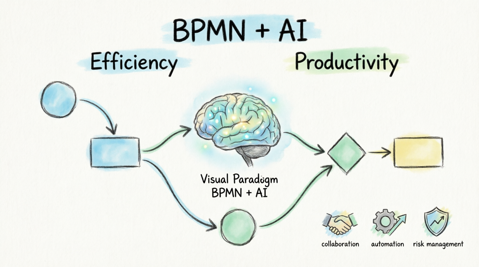
Following numerous revisions, the Object Management Group (OMG) published BPMN 2.0 in 2010, introducing execution semantics that enable technical automation via process engines. Today, BPMN 2.0.1 is established as an international norm (ISO/IEC 19510:2013). To fully leverage this standard, modern organizations rely on advanced tooling. Tooling: Visual Paradigm BPMN + AI represents the next evolution in process modeling, combining the rigorous BPMN 2.0 standard with groundbreaking artificial intelligence to accelerate diagram creation, ensure consistency, and transform static models into dynamic, actionable workflows.
How BPMN Helps Map Business Processes
Using the BPMN standard allows for an effective, end-to-end representation of business processes using a familiar flowchart method. Building a BPMN diagram begins with creating a “pool,” which can be subdivided into any number of “lanes.” Depending on the diagram’s complexity, multiple pools can be created to represent different participants. Every process model starts with at least one start event and concludes with one or more end events. The space between these events is populated with activities, gateways, intermediate events, and other artifacts.
Adhering to precise modeling guidelines ensures the correct use of elements and consistent documentation. This rigor helps boost productivity, allows organizations to adapt to changing conditions, and provides a sustainable competitive advantage.
This is where Tooling: Visual Paradigm BPMN + AI truly shines. Instead of manually dragging and dropping every element, users can leverage AI-powered features to generate industry-specific BPMN diagrams effortlessly by simply entering natural language text commands. Visual Paradigm’s AI assists in auto-suggesting process steps, identifying missing connections, and ensuring adherence to BPMN 2.0 standards, saving significant time and effort while guaranteeing greater consistency in your process models.
Key Benefits of BPMN (Enhanced by Visual Paradigm)
Adopting BPMN, especially when supported by intelligent tooling like Visual Paradigm, provides considerable added value to organizations through several core benefits:
-
Visualization: Access a clear, uniform visualization of your business processes using standardized symbols. Visual Paradigm’s intuitive canvas and AI-assisted layout tools make it easier for everyone to understand and smoothly navigate the process flow.
-
Communication: Significantly improve communication between diverse stakeholders. This widely adopted standard is suitable for both IT and business domains, fostering a shared understanding that Visual Paradigm further bridges with real-time collaboration features.
-
Identification: Easily identify bottlenecks and inefficient process steps. By analyzing the process flow, you can pinpoint potential improvements. Visual Paradigm’s analytical tools can highlight redundancies, helping you increase efficiency and reduce costs simultaneously.
-
Process Automation: BPMN serves as the foundational basis for process automation. Visual Paradigm ensures your modeled processes are technically sound and seamlessly integrable into workflow management systems and process engines.
-
Standardized Documentation: Document and manage business processes in a standardized way. This facilitates knowledge management and the training of new employees, with all relevant information available in a uniform, AI-verified format.
-
Compliance and Risk Management: Better understand and manage compliance requirements and associated risks. The clear presentation of processes ensures regulations are adhered to, while Visual Paradigm allows you to explicitly map risk and control artifacts to specific process steps.
Designing Your BPMN Process: A Rich Set of Symbols
BPMN 2.0 contains a comprehensive library of elements. Tooling: Visual Paradigm BPMN + AI provides a rich, drag-and-drop palette of these symbols, complete with AI-driven auto-completion to make assembling your diagrams intuitive and error-free. Below is a detailed breakdown of the core components organized by category.
Events
Events represent occurring, business-relevant states. In BPMN 2.0, events can start a process, occur during a process, be caused by external triggers, or end a process.
| Icon | Element | Description |
|---|---|---|
 |
Start Event | Triggers the sequence flow of a diagram. |
 |
Intermediate Event | Pauses the sequence flow. The flow is only resumed when the specific event condition has occurred. |
 |
End Event | Terminates the sequence flow of a diagram. |
Activities
Activities represent individual process steps or work performed within the business process.
| Icon | Element | Description |
|---|---|---|
 |
Activity | Represents a single work step and is expressed in an active verb form. |
 |
Sub Process | Used to avoid cluttering the main diagram with complex sequences. It provides a detailed, nested flowchart description of complex activities on a deeper level. |
Gateways
Processes are rarely purely linear; they consist of splits and mergers, which are represented by gateways.
| Icon | Element | Description |
|---|---|---|
 |
Exclusive Gateway | Used when only one condition can occur (“either/or”). When merging, exactly one incoming process path must be satisfied. |
 |
Parallel Gateway | All outgoing process paths must be satisfied (“and”). The process flow can only continue once all incoming process paths have been fulfilled. |
 |
Inclusive Gateway | Used when one or more process paths can be followed (“and/or”). When merging, the flow waits for all previously triggered paths to complete. |
 |
Event-based Gateway | The process flow follows the path of the event that occurs first. |
Connectors
All flow elements in a BPMN process are connected by specific types of flows.
| Icon | Element | Description |
|---|---|---|
 |
Sequence Flows | Connect activities, events, and gateways within a process, illustrating the chronological sequence of execution. |
 |
Message Flows | Represent the exchange of information with external process participants. They are triggered by activities and can attach to other activities, pools, or new events. |
Pools & Lanes
Individual process steps are performed by specific participants, represented as organizational units, roles, IT systems, or services.
| Icon | Element | Description |
|---|---|---|
 |
Pool | Represents a superior process participant that coordinates the process flow within its boundaries. Pools cover the entire process and assign tasks to responsible lanes. |
 |
Lanes | Subdivisions within a pool that represent specific process participants, such as organizational units or roles. Individual tasks are modeled within the corresponding lane. |
Artifacts
Additional artifacts can be added to make the design of business processes even clearer without altering the actual process flow. Visual Paradigm makes it easy to attach these contextual elements to any core BPMN shape.
| Icon | Element | Description |
|---|---|---|
 |
Data Objects | Represent documents or data used or created during process steps. These can be physical paper documents or electronic data. |
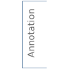 |
Annotation | Provides additional text to clarify BPMN elements, offering a better understanding of the process model directly within the diagram. |
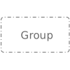 |
Group | A visual element that summarizes content-related objects to improve model comprehension without affecting the sequence flow. |
 |
Role | An abstraction of organizational positions or a summary of similar fields of activity, used to represent participants other than those modeled strictly as lanes. |
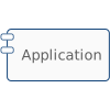 |
Application | Represents IT systems relevant to the execution of process steps, explicitly showing which software supports manual work. |
 |
Norm | Represents requirements for process execution, such as company-specific guidelines or official international standards. |
 |
Risk | Highlights hazards that can occur during process execution, supporting process-oriented risk management. |
 |
Control | Represents regulatory activities aimed at minimizing risks, supporting internal control systems within the modeled process. |
Example
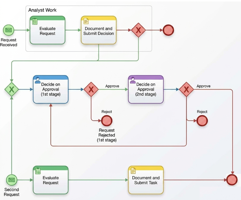
Diagram Description
-
- Visual Structure: The process is organized into distinct phases, using a sequential layout from left to right and top to bottom.
- Containers & Tasks: Tasks are represented by rounded rectangles with colored header bars. At the top, a gray boundary box labeled “Analyst Work” groups the initial data processing.
- Connectors: Colored directional arrows (green, blue, and red) trace the sequential paths, loops, and terminal branches.
- BPMN Elements: Standard symbols are utilized, including message start events (envelope icons), intermediate events (circular nodes), user task badges (person icons), exclusive gateways (red diamonds with ‘X’), and end events (thick-bordered red circles).
Phase 1: Preparation & Initial Analysis
- Process Trigger: The process kicks off when a message is received (Request Received).
- Initial Evaluation: An analyst reviews the data via the Evaluate Request task.
- Documentation & Splitting: The analyst documents the outcome (Document and Submit Decision). The flow passes through an exclusive gateway splitting logic:
- One path routes down into the formal approval sequence.
- A parallel or alternative branch safely concludes or logs data at a local end event node.
Phase 2: First-Stage Verification
- First-Stage Review: The request lands on the desk of the first reviewer (Decide on Approval – 1st stage).
- 1st Stage Gateway Evaluation:
- Approve Branch: If acceptable, the flow moves forward to the second-stage review.
- Reject Branch: If unacceptable, the request routes to a dedicated Request Rejected (1st stage) End Event, cleanly terminating that invalid path.
Phase 3: Second-Stage Review & Loopback Logic
- Second-Stage Review: The senior reviewer evaluates the request via the Decide on Approval (2nd stage) task.
- 2nd Stage Gateway Evaluation:
- Approve Branch: If fully approved, the token moves directly to the final terminal state.
- Reject Branch: Instead of a hard termination, a rejection here acts as a Loopback Routing. The flow loops all the way back into the entry point of the 1st stage approval, giving the initial reviewers a chance to rectify, update, or re-evaluate the request based on senior feedback.
Phase 4: Secondary Track & Final Completion
- Second Request Trigger: An independent message start event (Second Request) triggers a localized track.
- Parallel Processing: It undergoes its own evaluation loop (Evaluate Request → Document and Submit Task).
- Final Process Resolution: Both the primary approved branch (from Stage 2) and this secondary track successfully converge at the absolute final node: Process Completed – Final Approval, indicating the overall case file is officially closed and active.
Conclusion
The strategic use of BPMN models is a transformative approach to improving organizational efficiency and productivity. By providing a standardized, intuitive, and universally understood visual language, BPMN eliminates communication silos between business and IT teams. However, the true potential of BPMN is unlocked when paired with advanced Tooling: Visual Paradigm BPMN + AI.
Whether the goal is to document existing workflows, identify operational bottlenecks, ensure regulatory compliance, or lay the groundwork for robust process automation, Visual Paradigm’s AI-driven features accelerate the modeling process, enforce standardization, and provide intelligent insights. By leveraging this powerful combination, organizations can generate, refine, and manage their business processes effortlessly, ensuring they remain agile, optimized, and aligned with strategic objectives in an ever-evolving market.
Reference List
-
What is BPMN?: A foundational overview of the Business Process Modeling Notation and its core concepts.
-
How to Draw BPMN Diagram?: A step-by-step tutorial on creating business process diagrams using Visual Paradigm.
-
Business Process Design with Powerful BPMN Software: An exploration of Visual Paradigm’s intuitive BPMN 2.0 modeler and its professional design features.
-
BPMN Activity Types Explained: A detailed guide to understanding and modeling different BPMN activity types effectively.
-
Introduction to BPMN using Visual Paradigm: A modern guide highlighting the benefits of using Visual Paradigm for intuitive BPMN 2.0 modeling and process drill-down.
Related posts:
 Hands-On Review: Automating Inventory Management with BPMN Conditional Start Events
 The Consultant’s Playbook: Conducting Live Process Mapping Workshops with AI
 Value Stream Mapping Feels Hard? Let an AI Tool Do the Heavy Lifting!
 Mastering BPMN: A Comprehensive Guide to Core Flow Objects and Process Modeling
