
Mastery of UML Activity Diagrams: A Comprehensive Guide to Best Practices and VPasCode Implementation
In the realm of software engineering and system architecture, the Activity Diagram stands as one of the most powerful tools for visualizing dynamic behavior. Unlike static structure diagrams that show how components fit together, activity diagrams illustrate how a system functions, tracing the flow of control and data through complex business processes.
However, creating a diagram that is merely “drawing” rather than “modeling” is a common pitfall. To bridge the gap between a sketch and a rigorous engineering specification, we must adhere to strict guidelines regarding clarity, robustness, and responsibility. This tutorial explores these best practices and demonstrates how to implement them using the VPasCode approach within Visual Paradigm.
Phase 1: The Foundation of Clarity
The first principle of a successful activity diagram is immediate understandability. If a stakeholder cannot grasp the purpose of the diagram in ten seconds, the model has failed its primary objective.
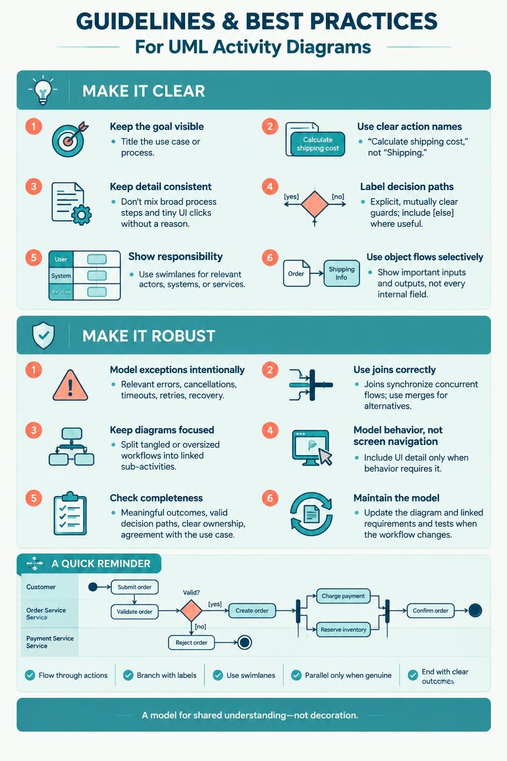
1. Keep the Goal Visible
A diagram should never exist in a vacuum. It must be anchored by a clear title that identifies the specific use case or business process being modeled. For instance, a diagram titled “Process” is ambiguous, whereas Calculate Shipping Cost or Process Return provides immediate context.
2. Use Clear Action Names
Naming conventions are critical for semantic clarity. You should prefer explicit verbs over vague nouns. Instead of labeling a node “Shipping,” which could mean the status, the department, or the method, use Calculate shipping cost. This action-oriented naming convention ensures that the diagram represents behavior, not just entities.
3. Maintain Consistent Detail Levels
One of the most frequent errors in modeling is the “zoom level” mismatch. You must avoid mixing high-level business steps (e.g., Fulfill order) with low-level technical implementation details (e.g., Press the blue button) unless that granularity is specifically required for the analysis. Consistency ensures the diagram remains readable and focused on the intended scope.
Phase 2: Robust Logic and Decision Making
A simple linear flow is easy to read, but real-world systems are rarely linear. They involve complex decision trees, parallel processing, and exception handling. A robust diagram anticipates these variations.
4. Label Decision Paths Explicitly
Decision nodes (the diamond shape) are the branching points of your logic. Every outgoing path from a decision node must have a guard condition (a label indicating “true” or “false”, or specific values). Crucially, you must ensure these paths are mutually exclusive and collectively exhaustive. If a condition does not cover all possibilities, you must explicitly include an [else] or default path to prevent the flow from hanging.
5. Model Exceptions Intentionally
It is tempting to model only the “Happy Path”—the scenario where everything goes right. However, a professional activity diagram must account for failure. You should include relevant errors, cancellations, timeouts, and recovery paths. While you don’t need to model every technical crash, you must model the system’s response to critical failures, such as Order Cancelled or Payment Timeout.
6. Use Joins Correctly (Avoid Ambiguous Joins)
When branches of logic converge, you use a Join node. However, there is a strict semantic difference between a Join and a Merge:
- Merge: Used for alternatives. If the flow comes from path A or path B, merge them. The flow is a choice.
- Join: Used for synchronization. If the flow requires both path A and path B to be completed before proceeding, use a Join. The flow waits for all inputs.
Phase 3: Responsibility and Scope
Complex systems involve multiple actors. To prevent the diagram from becoming a tangled mess, we use structural elements to organize the workflow.
7. Show Responsibility with Swimlanes
Swimlanes are the primary tool for organizing activity diagrams. By dividing the diagram into lanes for the User, the System, or external Services, you make handoffs explicit. This is vital for reviewing requirements because it answers the question: “Who is responsible for this step?”
8. Use Object Flows Selectively
Activity diagrams often show the movement of data (Object Flows). While useful, data modeling should not clutter the control flow. Show inputs and outputs (e.g., an Order document entering the process) only when the data state is critical to the requirement. Do not add every internal variable or field, or the diagram will become unreadable.
Phase 4: Implementation with VPasCode
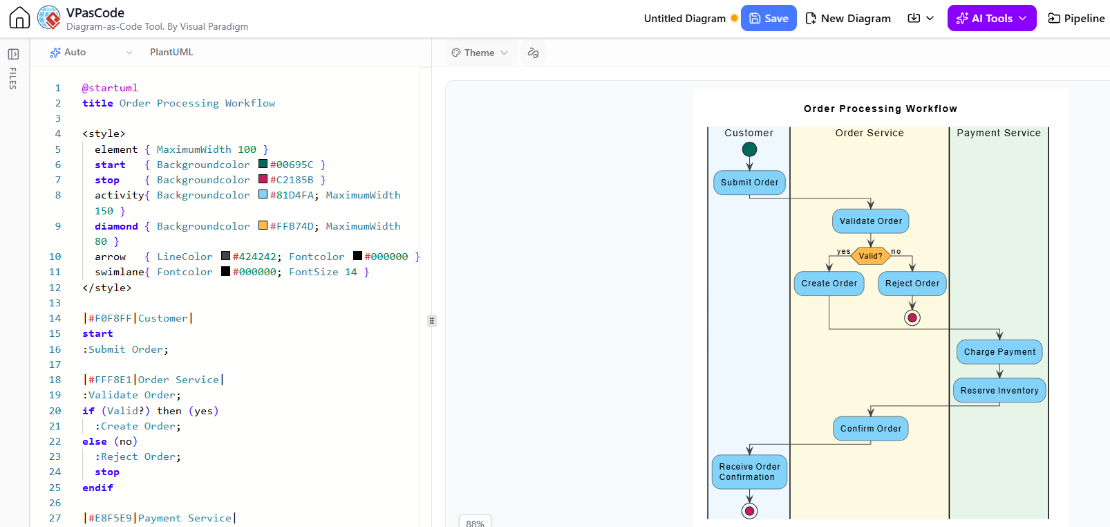
While drag-and-drop interfaces are convenient, the VPasCode approach (Modeling as Code) offers precision and version control. Below is a conceptual representation of how a robust workflow is structured using code-like syntax, adhering to the guidelines above.
Consider a scenario involving a Customer, an Order Service, and a Payment Service. We define the swimlanes and the logic flow.
@startuml
title Order Processing Workflow

<style>
  element { MaximumWidth 100 }
  start   { Backgroundcolor #00695C }
  stop    { Backgroundcolor #C2185B }
  activity{ Backgroundcolor #81D4FA; MaximumWidth 150 }
  diamond { Backgroundcolor #FFB74D; MaximumWidth 80 }
  arrow   { LineColor #424242; Fontcolor #000000 }
  swimlane{ Fontcolor #000000; FontSize 14 }
</style>

|#F0F8FF|Customer|
start
:Submit Order;

|#FFF8E1|Order Service|
:Validate Order;
if (Valid?) then (yes)
  :Create Order;
else (no)
  :Reject Order;
  stop
endif

|#E8F5E9|Payment Service|
:Charge Payment;
:Reserve Inventory;

|#FFF8E1|Order Service|
:Confirm Order;

|#F0F8FF|Customer|
:Receive Order Confirmation;
stop

@enduml
Phase 5: Completeness and Maintenance
The final stage of the modeling lifecycle is verification and maintenance. An activity diagram is a living model, not a static decoration.
Check Completeness and Consistency: Ensure that every start node leads to a meaningful outcome. There should be no “dead ends” where the flow stops without a decision or an error. Furthermore, the diagram must agree with the written use case. If the text says “Retry on failure,” but the diagram stops at the error, the model is inconsistent.
Avoid Screen Navigation Confusion: Do not confuse process flow with screen navigation. Do not model “Click Next Button” unless the button click is the specific behavior being tested. Instead, model the logical outcome, such as Proceed to Payment.
Maintain the Model: If the workflow changes—such as a new tax calculation rule or a change in payment provider—the diagram must be updated immediately. An outdated diagram is worse than no diagram, as it actively misleads the development team.
Summary
By following these guidelines—keeping goals visible, maintaining consistent detail, labeling decisions, and using swimlanes for responsibility—you transform an activity diagram from a simple flowchart into a rigorous system specification. Whether you are drawing manually or generating code with VPasCode, the logic remains the same: clarity, robustness, and precision.