
From Mind Maps to BPMN: Mastering Diagram Conversion with AI
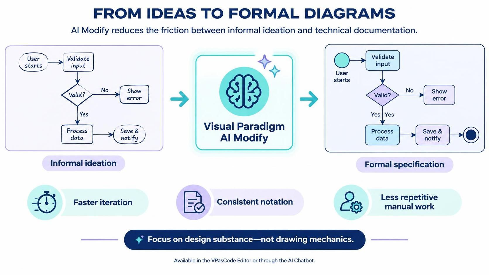
In the realm of software architecture and systems analysis, a persistent challenge has always been the transition from “rough sketching” to “formal engineering.” For years, analysts and architects have spent valuable time manually redrawing diagrams to fit specific documentation standards. Visual Paradigm AI Modify disrupts this workflow by acting as a semantic bridge, instantly converting an informal ideation sketch into a rigorous, formal specification.
This tutorial explores the concept of Diagram Type Conversion, demonstrating how to leverage AI to preserve the logic of your ideas while automatically enforcing the strict syntax of industry-standard modeling languages like BPMN 2.0.
The Concept: Bridging the Friction Gap
Traditionally, the modeling process is fragmented. An architect might start with a casual flowchart to capture a user journey (Informal Ideation). However, when it comes time to hand this off to developers, the diagram must often be converted into a formal BPMN (Business Process Model and Notation) diagram to ensure compliance with technical standards.
Without AI, this conversion requires:
- Manually redrawing nodes.
- Correcting arrow directions and connectors.
- Ensuring every diamond (decision) has a valid “Yes” and “No” path.
- Adding explicit start and end event markers.
AI Modify automates this transformation. It understands that a diamond shape represents a decision, regardless of whether you are drawing in a generic flowchart style or a BPMN style. It translates the intent of the diagram, not just the shapes.
Step-by-Step: The Transformation Process
Let’s walk through the logical flow of a “Data Validation Process” as depicted in the system architecture. We will observe how the AI interprets an informal sketch and elevates it to a formal specification.
1. The Input: Informal Ideation
Consider a basic, unstyled diagram representing a user workflow. In this “sketch” phase, the focus is purely on the logic:
- A starting point (User starts).
- An action to validate input.
- A decision point asking “Valid?”.
- Branching paths for “Yes” and “No”.
- Final actions like “Process data” and “Save & notify”.
In this state, the diagram might lack standard notation. It might be missing specific “End” markers, or the decision diamonds might not have explicit labels for their outgoing paths.
2. The Engine: Visual Paradigm AI Modify
When you trigger the AI Modify feature (via the VPasCode Editor or AI Chatbot), the system analyzes the topology of the diagram. It does not simply “redraw” the image; it parses the semantic relationships.
It detects that:
- The “User starts” node is an Start Event.
- The “Valid?” diamond is a Exclusive Gateway.
- The “Process data” box is a Task.
3. The Output: Formal Specification
The result is a diagram that adheres to formal standards (typically BPMN 2.0). The AI automatically applies the correct visual syntax:
- Start Event: A simple circle is generated to mark the entry point.
- Gateways: The decision diamond is refined. Crucially, the AI ensures that all outgoing paths are labeled correctly (e.g., “Yes” and “No”).
- End Event: A thick-bordered circle or filled circle is added to signify the successful termination of the process.
- Flow Lines: Arrows are automatically routed to prevent overlapping, ensuring the diagram is readable and professional.
Technical Syntax: The Underlying Logic
While Visual Paradigm handles the visual rendering, it is helpful for architects to understand the logical structure being generated. The AI essentially translates your visual graph into a structured logic tree. The following pseudo-code represents the logic the AI infers from the diagram:
// Workflow Logic Inference
// Source: Informal Sketch -> Target: Formal BPMN

Start_Event: User_Start

Action: Validate_Input
  --> Decision: Is_Valid?

  Path: NO
    Action: Show_Error
    --> End_Event (Process Termination)

  Path: YES
    Action: Process_Data
    --> Action: Save_And_Notify
    --> End_Event (Process Completion)
By converting your informal nodes into this structured logic, the AI ensures that the diagram is not just a picture, but a machine-readable specification that can be executed or simulated.
Key Benefits of AI-Driven Conversion
The shift from manual redrawing to AI-driven conversion offers three distinct advantages for technical teams:
Faster Iteration
Architects can change the logic of a process (e.g., adding a new validation step) in a rough sketch and instantly update the formal documentation. There is no need to wait for a designer to redraw the diagram.
Consistent Notation
Human error often leads to inconsistent diagrams (e.g., using a square for a decision instead of a diamond). AI Modify enforces strict adherence to the selected standard (like BPMN), ensuring that every diagram in your repository looks uniform.
Reduced Repetitive Work
By removing the mechanical act of “drawing lines” and “aligning boxes,” teams can focus on the substance of the design. The AI handles the “mechanics of drawing.”
Conclusion
The transition from “Ideas to Formal Diagrams” is no longer a bottleneck. With Visual Paradigm AI Modify, the distinction between a rough sketch and a technical blueprint dissolves. By preserving the underlying logic of your workflows while automatically applying the correct syntax and structure, you ensure that your documentation remains accurate, consistent, and aligned with your project’s current stage. Whether you are refining user journeys or detailing complex system interactions, this tool empowers you to focus on the substance of your design rather than the mechanics of drawing it.