
From Messy Problem to Clear Flowchart: Mastering Computational Thinking with Visual Paradigm
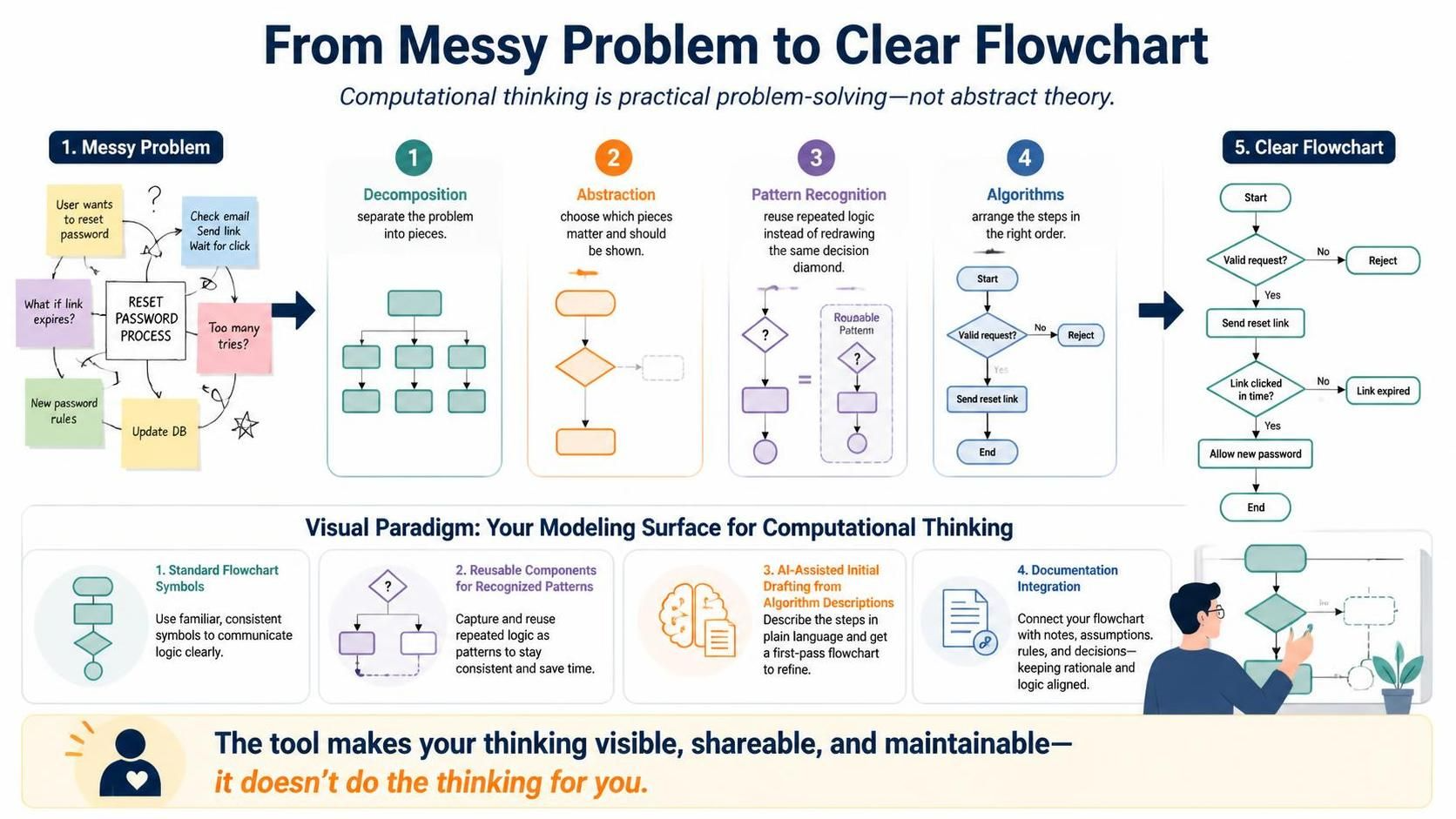
Transitioning from a chaotic, unstructured problem statement to a polished, professional flowchart is not magic—it is a disciplined engineering process. Visual Paradigm supports this journey by providing the specific modeling surface required to execute the four pillars of computational thinking: decomposition, abstraction, pattern recognition, and algorithms.
This tutorial explores how to leverage the Visual Paradigm Flowchart and AI tools (specifically VPasCode) to transform a “messy problem” into a clear, maintainable system architecture.
1. The Architecture of Thought: The 4-Step Process
The diagram illustrates a linear progression where complexity is systematically reduced. Here is the technical breakdown of each stage.
Step 1: Decomposition (Separate the Problem)
Every complex system begins as a “messy problem”—a collection of requirements, edge cases, and user intents. The first step is decomposition.
- Concept: Break the central entity (e.g., “Reset Password Process”) into its constituent parts.
- Visual Paradigm Application: Instead of drawing one giant node, you identify the distinct functional blocks: Check Email, Validate Rules, and Update DB.
- Goal: To convert a monolithic blob of text into manageable, discrete data points.
Step 2: Abstraction (Choose Which Pieces to Show)
Once decomposed, you must filter the noise. Not every detail belongs in the primary model. This is abstraction.
- Concept: Decide which components are critical for the high-level flow and which are implementation details to be hidden or deferred.
- Visual Paradigm Application: You choose to show the “Valid Request” diamond but abstract away the specific database query syntax. You focus on the control flow rather than the data structure.
- Goal: To create a view that is readable by stakeholders, removing irrelevant complexity.
Step 3: Pattern Recognition (Reuse Repeated Logic)
Human beings are prone to repetitive errors. If you find yourself drawing the same decision diamond or loop structure repeatedly, you are missing a pattern. This is pattern recognition.
- Concept: Identify recurring logic structures (e.g., “Retry Logic” or “Error Handling”) and treat them as reusable components rather than static shapes.
- Visual Paradigm Application: The tool encourages you to capture this as a “Reusable Component” or “Roundable Pattern.” Instead of redrawing the logic for “Link Expired” five times, you define it once and reference it.
- Goal: To maintain consistency across the model and save time during updates.
Step 4: Algorithms (Arrange Steps in Order)
The final step is algorithmization. This is where you define the precise sequence of operations.
- Concept: Arrange the decomposed, abstracted, and patterned pieces into a logical execution path.
- Visual Paradigm Application: You connect the Start node to the “Valid Request” decision, then to “Send Reset Link,” and finally to the “End” state, ensuring every branch (Yes/No) is accounted for.
- Goal: To produce a deterministic flowchart that can be executed or reviewed without ambiguity.
2. Visual Paradigm: The Modeling Surface
Visual Paradigm is not just a drawing tool; it is a platform designed to support this specific cognitive workflow. It integrates four key features that bridge the gap between abstract thought and concrete diagrams.
1. Standard Flowchart Symbols
Communication requires a shared language. The tool provides a library of standard symbols (Terminators, Processes, Decisions, Data). Using these ensures that your diagram is instantly understood by any technical stakeholder, adhering to industry standards.
2. Reusable Components for Recognized Patterns
As mentioned in Step 3, efficiency is key. The tool allows you to capture repeated logic as Reusable Components. This means you can define a “Link Expired” logic block once and reuse it across multiple processes, ensuring that if the logic changes, it updates everywhere.
3. AI-Assisted Initial Drafting from Algorithm Descriptions
Visual Paradigm integrates VPasCode (Visual Paradigm as Code). This feature allows you to describe your logic in plain text or pseudocode, and the AI generates the initial draft of the flowchart. This is the fastest way to move from “Algorithm Description” to “Visual Model.”
4. Documentation Integration
A flowchart is useless if the rationale is lost. The tool integrates Documentation directly with the model. You can attach notes, assumptions, and rules to specific nodes, keeping the why of the decision tied to the what of the diagram.
3. Practical Application: VPasCode Example
To demonstrate the power of the “Algorithms” step combined with AI assistance, consider how you might define a “Password Reset” process using VPasCode. Instead of dragging and dropping shapes manually, you can describe the algorithm:
flowchart TD
    A[Start] --> B{Valid Request?}
    B -- No --> C[Reject]
    B -- Yes --> D[Send Reset Link]
    D --> E{Link Clicked in Time?}
    E -- No --> F[Link Expired]
    E -- Yes --> G[Allow New Password]
    G --> H[End]
In Visual Paradigm, you can input this logic directly, and the AI engine renders the “Clear Flowchart” shown in the reference diagram, ensuring that the visual representation perfectly matches the logical intent.
Conclusion: Making Thinking Visible
The ultimate value of this system is not the diagram itself, but the clarity of thought it represents. As the diagram concludes: “The tool does not do the computational thinking for you, but it makes the results of that thinking visible, shareable, and maintainable.”
By strictly following the decomposition, abstraction, pattern recognition, and algorithm steps within Visual Paradigm, you ensure that your system architecture is robust, your logic is sound, and your documentation is precise.