
Mastering BPMN: Sequence Flows vs. Message Flows for Clear Process Modeling
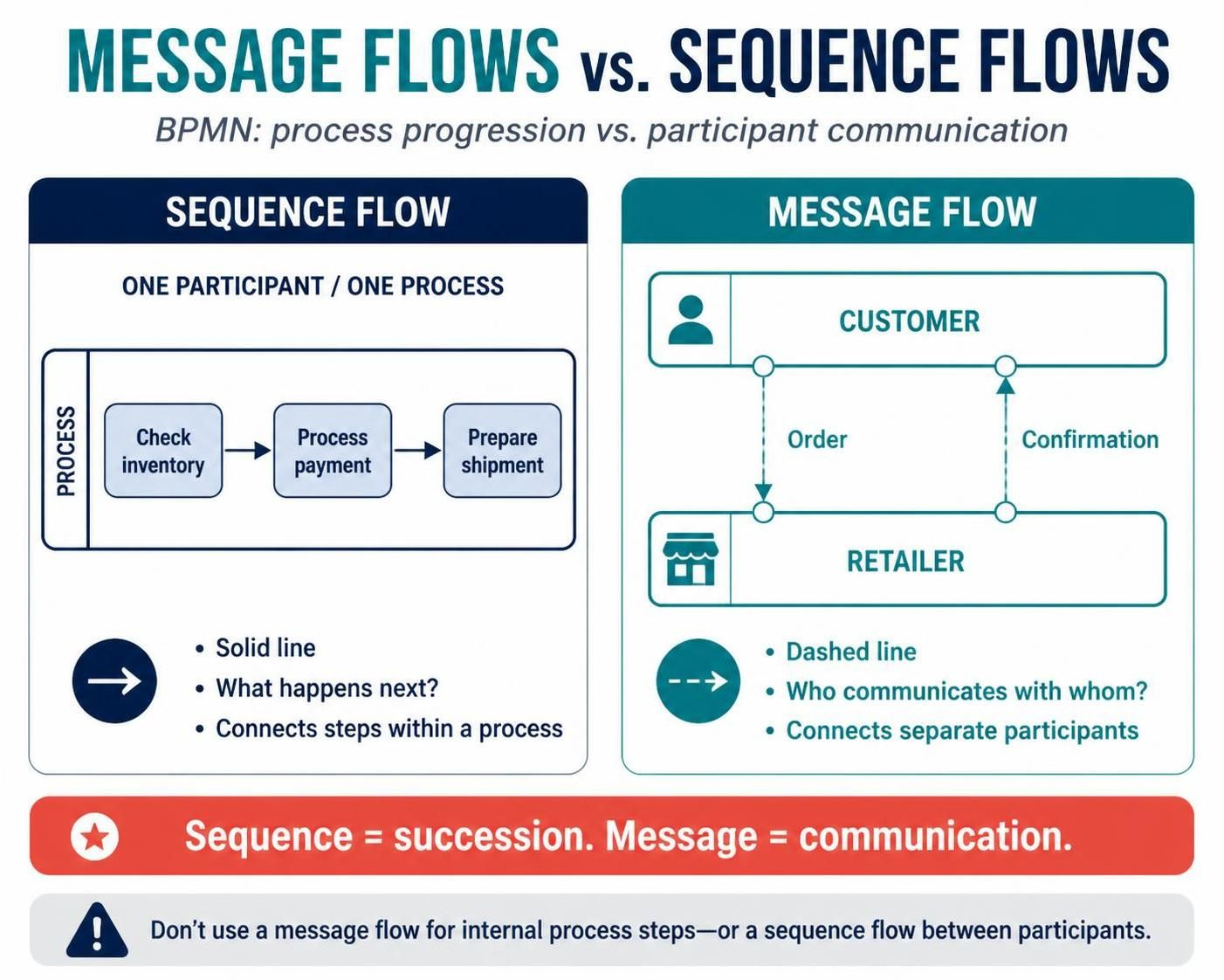
In the world of Business Process Model and Notation (BPMN), precision is everything. While BPMN offers a standardized visual language for business processes, it contains specific elements that, if confused, can render a diagram invalid in automation tools or simply misleading to stakeholders.
The most common point of confusion for new and intermediate modelers is the distinction between Sequence Flows and Message Flows. Visually, they both look like arrows connecting shapes, but they represent fundamentally different mechanics of time and interaction.
This tutorial walks you through the architecture of these two flows, explaining when to use each one to ensure your diagrams are robust, accurate, and ready for execution.
The Core Distinction: Succession vs. Communication
To understand the difference, we must look at the underlying architecture of a BPMN process. A diagram is not just a drawing; it is a set of instructions for a system. Therefore, every line represents a specific type of dependency.
1. Sequence Flow: The Internal Rhythm
Sequence Flow represents the order of operations. It dictates “what happens next.” This flow is the internal heartbeat of a process, ensuring that steps are executed in a logical, sequential order.
- Scope: It exists strictly within a single Process or a single Participant (Pools/Lanes).
- Visuals: Represented by a solid line with a filled arrowhead.
- Function: It connects Activity to Activity, or Task to Gateway. It signifies that the completion of the previous step triggers the start of the next.
Imagine a manufacturing line. Once the “Check Inventory” step is finished, the machine automatically moves to “Process Payment.” This is a sequence flow because it is a direct, internal progression of work.
2. Message Flow: The External Bridge
Message Flow represents the transfer of information. It depicts communication between distinct entities. It answers the question: “Who is talking to whom?”
- Scope: It connects separate Participants (Pools). It cannot stay within a single pool.
- Visuals: Represented by a dashed line with an open arrowhead.
- Function: It signifies an asynchronous exchange. For example, a Customer sends an Order to a Retailer. The Customer is not “waiting” for the Retailer to finish before they exist; they are simply communicating a piece of data.
Message flows are the bridges between different organizations, departments, or systems. They indicate that a message has been sent, but the receiving party does not necessarily begin their process immediately.
Visual Syntax and Implementation Rules
In modeling tools like Visual Paradigm or Camunda, the syntax rules are strict. Using the wrong connector type is often treated as a syntax error.
Visual Comparison Table
| Feature | Sequence Flow | Message Flow |
|---|---|---|
| Line Style | Solid Line | Dashed Line |
| Arrowhead | Filled (Triangle) | Open (Triangle) |
| Connection Scope | Same Pool (Internal) | Different Pools (External) |
| Meaning | Next Step | Communication |
Why Mixing Them Up Breaks the Model
The most dangerous error in BPMN modeling is crossing the boundaries of the participants.
- Connecting Pools with Sequence Flow: If you draw a solid line between the “Customer” pool and the “Retailer” pool, you are telling the automation engine that the Customer process controls the Retailer process. This is logically impossible. The Customer cannot trigger the Retailer’s internal logic directly; they can only send a message.
- Connecting Activities with Message Flow: If you use a dashed line between two tasks within the same lane, you are telling the system that these two steps are unrelated to the process flow, or that they are communicating asynchronously in a way that doesn’t represent a direct sequence. This breaks the execution logic.
Remember the golden rule: Sequence = Succession. Message = Communication.
Architecture of a Correct Interaction
Let’s look at the standard pattern for an interaction between a Customer and a Retailer. This is how the architecture should be structured:
[CUSTOMER POOL]               [RETAILER POOL]
-------------------------------------------------------
  (Start Event)                 (Start Event)
        |                             ^
        |                             |
        |    [Message Flow: "Order"]  |
        |---------------------------> |
        |                             |
        |                             | [Receive Task]
        |                             |
        |                             | [Process Order]
        |                             |
        |                             |
        |    [Message Flow: "Confirm"]|
        |<--------------------------  |
        |                             |
        |                             |
  (End Event)                 (End Event)
In this diagram, the dashed lines bridge the gap between the two pools, indicating that information is passing between them. Inside the pools, if there were internal tasks, they would be connected by solid lines.
Conclusion
Mastering the difference between Sequence and Message flows is the first step toward creating professional, executable BPMN diagrams. By strictly adhering to the rule that Sequence Flows manage internal steps and Message Flows manage external communication, you ensure your models are logically sound and technically valid for automation tools.