
Mastering Order Fulfillment with VPasCode: AI-Driven Flowcharts in PlantUML
In the rapidly evolving landscape of business analysis and software architecture, the gap between conceptual thinking and executable models has never been wider. Yet, tools like Visual Paradigm’s VPasCode are bridging this divide by allowing analysts to write code that automatically renders into professional-grade diagrams. This tutorial explores a classic business process scenario—the Order Fulfillment System—using PlantUML Activity Diagrams. We will dissect the syntax, the logical flow, and the architectural implications of managing inventory decisions within a system.
1. The Architecture of VPasCode and PlantUML
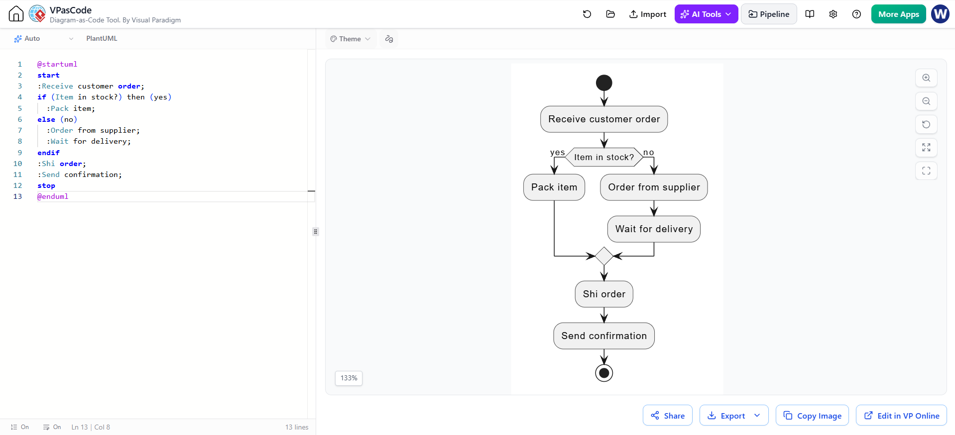
The screenshot provided illustrates the core philosophy of Diagram-as-Code. On the left, we see the source text, a concise set of instructions written in the PlantUML language. On the right, the AI Tools engine of Visual Paradigm interprets this text to render a precise Activity Diagram. This dual-view approach ensures that the logic remains human-readable while the visualization remains consistent and error-free.
This specific example demonstrates a Control Flow diagram. Unlike a Sequence Diagram, which focuses on time and object interactions, this diagram focuses on the state changes and decision paths of a single transaction: receiving an order and ensuring it reaches the customer.
2. Deconstructing the Process Flow
Let’s walk through the logic step-by-step, analyzing the interaction between the business rules and the technical syntax.
2.1 Initialization and Entry
Every business process needs a trigger. In our diagram, this is represented by the start node. The first action is the receipt of an order from a customer.
start
:Receive customer order;
The colon (:) prefix in PlantUML denotes an action or activity node. This is where the process enters the system.
2.2 The Decision Logic (The Fork)
The heart of this system is the inventory check. The business logic dictates that the fulfillment path changes based on whether stock is available. In PlantUML, this is handled by the if statement.
if (Item in stock?) then (yes)
  :Pack item;
else (no)
  :Order from supplier;
  :Wait for delivery;
endif
Notice how the syntax maps directly to the visual diamond shape in the generated diagram:
- Condition:
(Item in stock?)represents the decision diamond. - Branching: The
then (yes)andelse (no)keywords determine the labels on the arrows leaving the diamond. - Sub-Process: The
elsebranch is more complex. It requires two sequential actions: ordering the supplier and waiting for delivery. VPasCode handles this nesting seamlessly.
2.3 Convergence and Exit
Regardless of whether the item was in stock or had to be ordered, the process must eventually converge to ship the product. The diagram shows the flow lines merging back into a single path, leading to the shipping and confirmation steps.
:Ship order;
:Send confirmation;
stop
The stop keyword marks the end node, signifying that the transaction is complete.
3. Visual Paradigm Integration
What makes this tutorial specifically relevant to Visual Paradigm is the integration of VPasCode and AI Tools. By utilizing the AI integration, users can describe a process in natural language or pseudocode, and the tool can often generate the corresponding PlantUML syntax. This lowers the barrier to entry for creating complex architecture diagrams.
The interface shown allows for real-time synchronization. If you modify the code to add a “Payment Verification” step, the diagram on the right updates instantly, ensuring that documentation never drifts from the actual system design.
4. Technical Best Practices for Activity Diagrams
When modeling business processes using VPasCode, consider these architectural guidelines:
- Atomic Actions: Keep the text within the
:action;tags concise. If a step is too complex, break it into a sub-process. - Clear Branching: Always label your
thenandelsebranches explicitly. This improves the readability of the generated graph, especially for stakeholders who may not know the code. - Consistency: Maintain a consistent style for your nodes. Use the same naming convention (e.g., Verb-Noun) for all actions.
Conclusion
By leveraging the power of VPasCode, we have transformed a simple text script into a robust Business Process model. This approach not only saves time but also ensures that the logic of the system is preserved exactly as intended, making it an invaluable tool for modern system architects and business analysts.