
Mastering BPMN Sequence Flow: The Backbone of Process Control Logic
In the world of Business Process Model and Notation (BPMN), visualizing the flow of work is just as important as the work itself. While data flows show how information moves between systems, Sequence Flow represents the heartbeat of the process: the logical order in which activities occur.
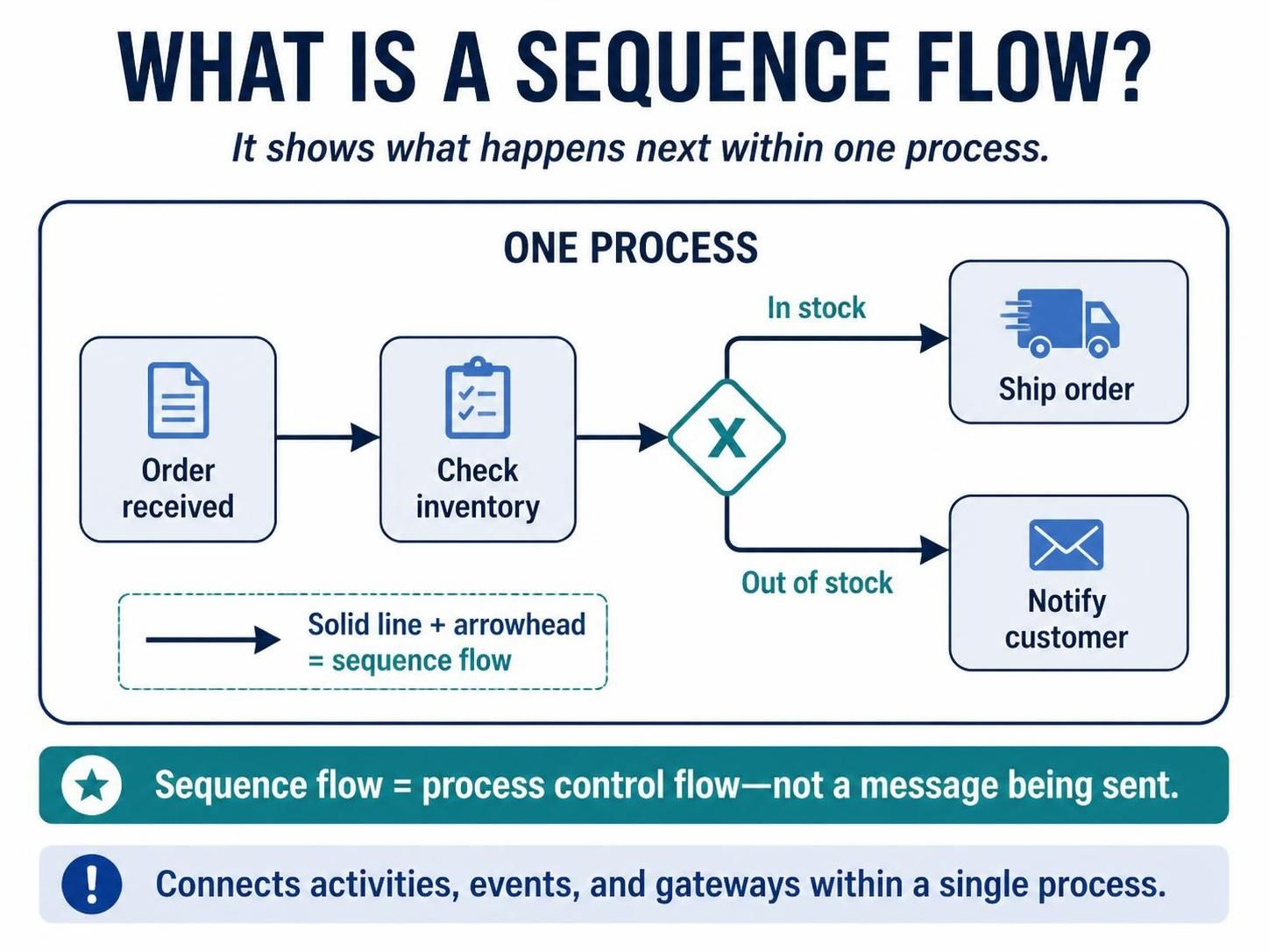
Based on the visual diagram provided, we will dissect what a sequence flow is, how it visually represents control logic, and the specific rules governing its behavior within a single process instance.
Defining Sequence Flow
A sequence flow is the standard connector used to link activities, events, and gateways. Its primary purpose is to dictate the order of execution. When you see a sequence flow, it answers the critical question: “What happens next?”
Unlike message flows, which indicate communication between different participants or systems, a sequence flow strictly controls the path of a single process. It represents the control flow, ensuring that step A is completed before step B begins.
Visual Syntax and Representation
In BPMN diagrams, the syntax is intuitive but strict. As highlighted in the diagram’s legend:
- Appearance: It is drawn as a solid line with a filled arrowhead.
- Directionality: The arrow indicates the direction of the process progression.
- Scope: It is contained entirely within a single process diagram.
The diagram illustrates a classic “Order Processing” scenario. The solid line connects the Order received event to the Check inventory task, which subsequently leads to a decision point.
Handling Conditional Logic with Gateways
One of the most powerful features of sequence flows is their ability to handle branching logic at Gateways. In the provided example, we encounter an Exclusive Gateway (XOR), represented by a diamond shape with an ‘X’ inside.
At this junction, the single incoming sequence flow splits into two alternative paths. The process can only take one of these paths based on a specific condition:
- Path A (In Stock): If the inventory check is successful, the sequence flow labeled “In stock” directs the process to the Ship order activity.
- Path B (Out of Stock): If the inventory check fails, the sequence flow labeled “Out of stock” directs the process to the Notify customer activity.
It is important to note that the labels on the sequence flows are not just decorative; they are the conditional expressions that determine which path the control flow follows.
Control Flow vs. Message Flow
A common misconception in process modeling is confusing the movement of a task with the movement of a message. The diagram explicitly clarifies this distinction in the teal banner:
“Sequence flow = process control flow—not a message being sent.”
If you were modeling a scenario where the Check inventory system sends an email to the Ship Order system, that would be a Message Flow (dashed line). However, since the diagram shows a single logical workflow where the “Ship order” activity is simply the next step for the same process instance, a solid sequence flow is the correct modeling choice.
Summary of Key Concepts
To recap the architectural rules shown in this tutorial:
- Connection Type: Connects elements (Tasks, Events, Gateways) within a single process.
- Visual Indicator: Solid line with an arrowhead.
- Function: Represents the sequential order and control flow of the business logic.
- Alternative Paths: Used at gateways to define mutually exclusive outcomes (e.g., In Stock vs. Out of Stock).
By mastering sequence flows, you ensure that your process models are not just pictures, but executable logic maps that accurately reflect the reality of business operations.