
Mastering BPMN Collaboration Diagrams with Visual Paradigm’s AI
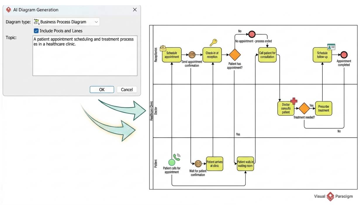
Business Process Model and Notation (BPMN) is the standard for visualizing complex workflows. However, creating a comprehensive Collaboration Diagram—one that clearly distinguishes between different organizational entities and their internal interactions—can be time-consuming. Visual Paradigm bridges this gap by integrating AI Assistance directly into its modeling environment, allowing you to generate editable, structured BPMN diagrams from simple text prompts.
This tutorial guides you through the architecture of AI-assisted modeling, explaining how to leverage the “AI Diagram Generation” interface to create a professional Healthcare Clinic process, and the specific rules you must follow to ensure your generated diagrams are accurate.
Understanding the AI-Assisted Workflow
The core of this feature lies in transforming natural language descriptions into structured visual models. The process begins with the AI Diagram Generation dialog, a specialized interface designed to parse your input into specific BPMN elements.
When you initiate this process, you define the Diagram Type (e.g., Business Process Diagram) and select the structural template. The critical checkbox here is “Include Pools and Lanes.” This tells the AI that you are not just modeling a single internal process, but a collaborative ecosystem involving multiple participants.
The Workflow Steps:
- Input Definition: You provide a Topic describing the process (e.g., “A patient appointment scheduling and treatment process in a healthcare clinic”).
- Generation: The AI engine analyzes the text and constructs a diagram using the specified pools and lanes.
- Refinement: The generated diagram is not a static image; it is an editable model. You can immediately adjust flow paths, change labels, or add new tasks.
Architecting Your Prompt: Pools, Lanes, and Flows
For the AI to generate a high-quality model, your prompt must be explicit about the desired structure. Ambiguity often leads to messy diagrams where all tasks are lumped into a single pool. You must clearly define the hierarchy of your collaboration.
Think of the structure as a hierarchy:
- Pools: Represent the primary participants or organizations (e.g., the Clinic, the Patient, or the Insurance Company).
- Lanes: Represent the specific roles or departments within those organizations (e.g., Receptionist, Doctor, Patient).
- Flows: Define how work moves between these roles.
Case Study: The Healthcare Clinic Process
Let’s break down the architecture of the diagram shown in the AI generation interface. The prompt describes a multi-party interaction that the AI interprets into a specific layout.
1. Defining the Participants (Pools)
The prompt explicitly requests separate pools. In this scenario, we have the Healthcare Clinic (the service provider) and the Patient (the consumer). In BPMN, these are distinct containers. Communication between them must use Message Flows, which are distinct from standard process flows.
2. Defining the Roles (Lanes)
Inside the Healthcare Clinic pool, the AI creates two lanes based on the prompt’s context:
- Receptionist: Handles the front-end interactions (scheduling, check-in).
- Doctor: Handles the clinical interactions (consultation, treatment).
3. The Sequence of Events
The AI maps the following logical sequence:
- Initiation: The Patient pool sends a message (“Patient calls for appointment”) to the Receptionist.
- Scheduling: The Receptionist performs the “Schedule appointment” task and sends a confirmation back to the Patient.
- Arrival: The Patient arrives at the clinic (Wait for patient confirmation).
- Triage: The Receptionist performs “Check-in at reception.” This triggers a decision point: “Patient has appointment?”
- Consultation: If the appointment exists, the flow moves to the Doctor lane (“Call patient for consultation”).
- Diagnosis: The Doctor performs the consultation. A decision diamond asks: “Treatment needed?”
- Resolution: If yes, the Doctor “Prescribes treatment.” If no, the process moves to follow-up scheduling.
Visualizing the Logic: The Generated Code Structure
To understand how the AI translates your prompt into a diagram, it helps to look at the logical structure it generates. Below is a representation of the logic flow described in the diagram.
// Patient Pool
Event: Patient calls for appointment
Message Flow -> Receptionist

// Receptionist Lane
Task: Schedule appointment
Task: Check-in at reception
Gateway: Patient has appointment? (Decision)
   -> No: Terminate (No appointment - process ended)
   -> Yes: Message Flow -> Doctor

// Doctor Lane
Task: Call patient for consultation
Task: Doctor consults patient
Gateway: Treatment needed? (Decision)
   -> Yes: Task: Prescribe treatment
   -> No: Task: Schedule follow-up
Refining the AI-Generated Model
It is crucial to treat the AI-generated diagram as a first draft. While the AI excels at creating the skeleton and basic logic, it may not capture every nuance of your specific business rules. You should perform a “Sanity Check” on the generated model:
- Verify Pool Separation: Ensure that independent participants (like the Patient and the Clinic) are in separate pools.
- Check Flow Types: Sequence flows (arrows) should generally stay within a single pool. Message flows (dashed lines with circles) are required for interactions between pools.
- Review Handoffs: Confirm that the task order reflects reality. For example, does the doctor consult the patient after they have checked in? If the diagram shows the doctor consulting before check-in, you must manually adjust the sequence.
- Layout Adjustments: AI tools often generate a vertical or horizontal flow that may need re-arranging for your specific audience. Use the desktop application’s layout tools to optimize the visual hierarchy.
Conclusion
Visual Paradigm’s AI assistance transforms the modeling process from a manual, time-intensive task into a collaborative dialogue. By clearly defining your participants (Pools) and roles (Lanes) in your prompt, you empower the AI to build a robust framework. This framework then serves as a solid foundation for you to refine, ensuring that your final diagram accurately reflects the complexity of real-world collaboration.