


1. What BPMN is
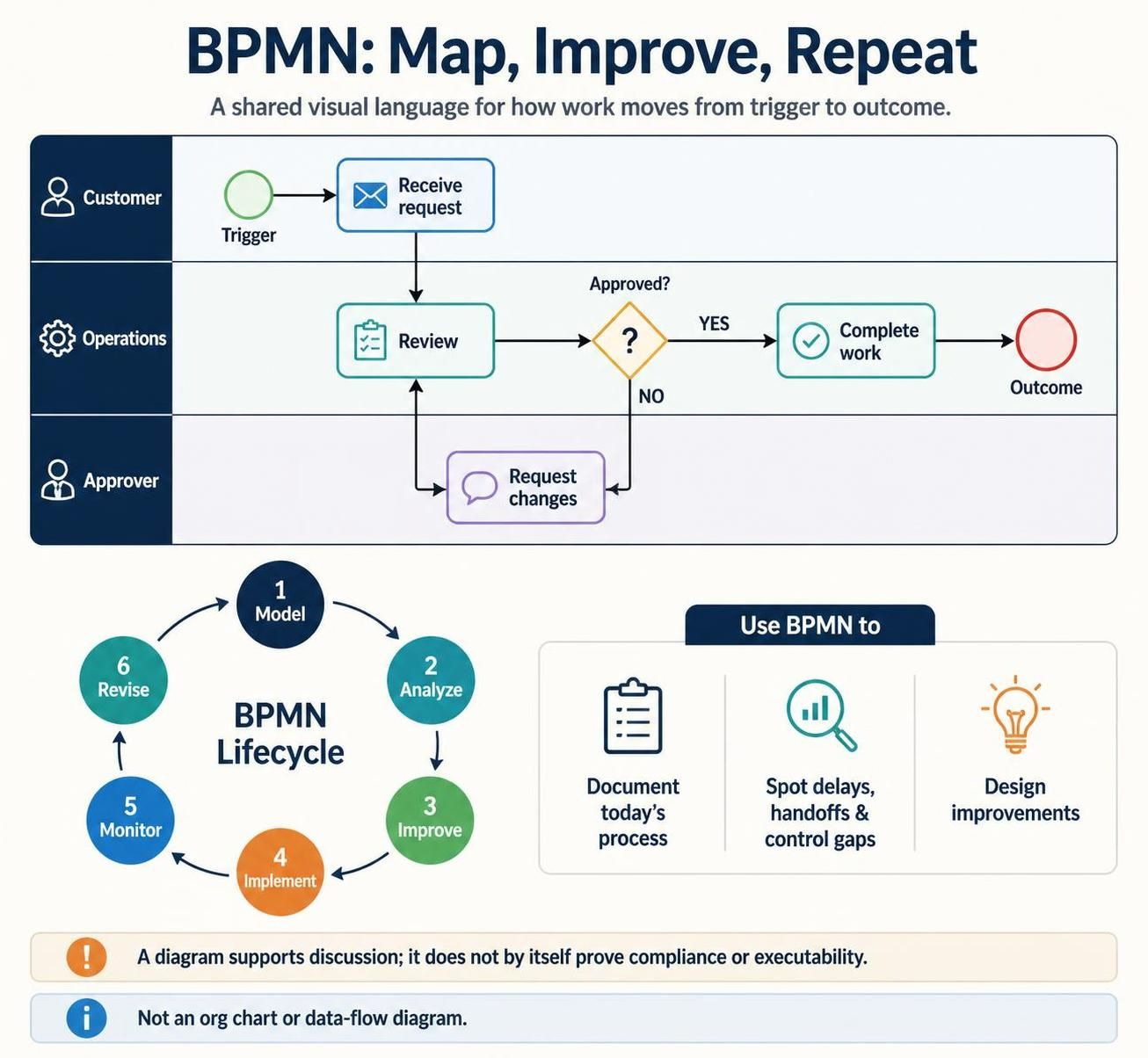
Business Process Model and Notation (BPMN) is a standardized visual language for describing a business process from its trigger through its outcome. It helps business stakeholders, analysts, process participants, and technical teams share a common understanding of how work proceeds, who performs it, where decisions happen, and how information moves. BPMN is useful for documenting current processes, discussing improvements, and creating more detailed models for implementation. It is not a substitute for an organizational chart or a data-flow diagram.
A practical BPM lifecycle is iterative: model → analyze → improve → implement → monitor → revise. Begin by clarifying the process, then use the model to identify bottlenecks, delays, unnecessary handoffs, and control gaps. BPMN can support discussion and analysis, but a diagram by itself does not prove a process is compliant or executable.
2. The core BPMN building blocks
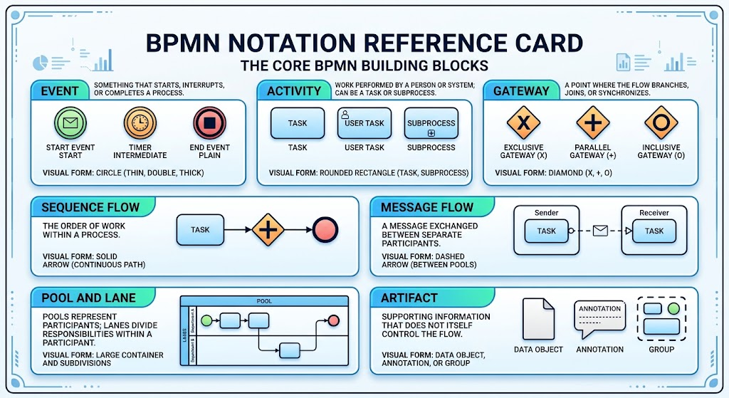
BPMN diagrams are built from flow objects, connecting objects, swimlanes, and artifacts.
| Element | What it means | Common visual form |
|---|---|---|
| Event | Something that starts, interrupts, or completes a process | Circle |
| Activity | Work performed by a person or system; can be a task or subprocess | Rounded rectangle |
| Gateway | A point where the flow branches, joins, or synchronizes | Diamond |
| Sequence flow | The order of work within a process | Solid arrow |
| Message flow | A message exchanged between separate participants | Dashed arrow |
| Pool and lane | Pools represent participants; lanes divide responsibilities within a participant | Large container and subdivisions |
| Artifact | Supporting information that does not itself control the flow | Data object, annotation, or group |
Events
Events show what happens during a process. A start event begins a process, an intermediate event occurs during it, and an end event marks an outcome. Event markers can indicate triggers or results such as messages, timers, errors, or compensation. Some events catch a trigger; others throw or produce one.
Choose an event that describes what actually happens. For example, use a message start event when receipt of a message triggers the process—not merely because the process involves email somewhere.
Activities and tasks
An activity is a unit of work. Use a task for a single step and a subprocess when a step contains meaningful detail that deserves its own diagram or a collapsed section in the high-level view. Subprocesses help keep an overview readable while preserving the option to model detail separately.
Task markers can convey additional behavior, such as repeated work, multiple instances, or compensation. Task types can also indicate whether work is performed by a person, a system, or manually. Choose a specialized type only when it adds useful meaning; otherwise, use a plain task and name the action clearly.
Gateways and branching
A gateway controls how the process branches or rejoins. Common patterns include:
-
Exclusive (XOR): one path is taken based on a condition.
-
Parallel (AND): multiple paths proceed concurrently and may later synchronize.
-
Inclusive (OR): one or more paths may be taken.
-
Event-based: the next path depends on which event occurs.
Label outgoing paths with clear conditions, such as Approved and Rejected. Make the default path explicit where one exists. Check that branches rejoin correctly: a parallel join, for example, should not be used as if it were a simple merge of mutually exclusive choices.
Flows, pools, and lanes
A sequence flow orders activities and events within a process. A message flow depicts communication between separate pools or participants; it is not a substitute for sequence flow inside one pool. An association links an annotation or artifact to a diagram element without directing process execution.
Use a pool for a participant such as a company, customer, or external provider. Use lanes inside a pool for roles, teams, or systems that perform the work. Assign each activity to the party accountable for doing it, rather than using lanes as decorative columns.
Data and supporting artifacts
Data objects can represent information needed by a task or produced by it. Data stores represent persistent data storage. Annotations add explanations, and groups visually organize related elements without changing the flow. Keep supporting detail focused: the diagram should show what is needed to understand the process, not become a substitute for every procedure document.
3. A reliable modeling workflow
-
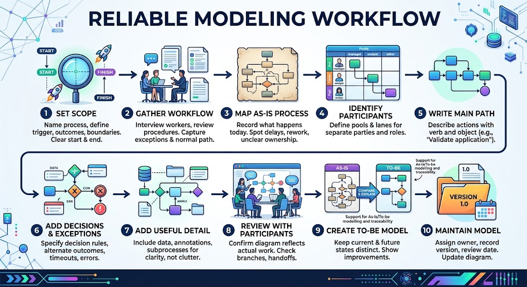
Set scope. Name the process, define its trigger, and identify the outcome and boundaries. A diagram should make clear where the process starts and finishes.
-
Gather the real workflow. Interview people who perform the work, review relevant procedures, and capture exceptions as well as the normal path.
-
Map the as-is process. Record what happens today before designing a better process. This makes delays, rework, unclear ownership, and unnecessary steps easier to spot.
-
Identify participants and responsibilities. Decide which parties belong in separate pools and which roles belong in lanes.
-
Write the main path in sequence. Describe each action with a verb and object—for example, “Validate application” or “Notify customer.”
-
Add decisions and exceptions. Specify decision conditions, alternate outcomes, timeouts, errors, cancellations, and other meaningful events.
-
Add only useful detail. Include data objects, stores, annotations, and subprocesses where they improve understanding.
-
Review with process participants. Confirm that the diagram reflects actual work and that every branch, handoff, and endpoint makes sense.
-
Create a to-be model if needed. Keep the current-state and proposed future-state versions distinct, then compare them to explain the intended changes. Visual Paradigm describes support for as-is/to-be modeling and traceability between versions.
-
Maintain the model. Assign an owner, record the version and review date, and update the diagram when the process changes.
4. Using Visual Paradigm with AI-assisted features
Visual Paradigm offers BPMN modeling and AI-assisted generation from natural-language descriptions. Its published product information describes generating an editable diagram from text, then refining it in the editor; some workflows also support conversational iteration and moving generated diagrams into Visual Paradigm’s desktop modeling environment.
Treat AI output as a first draft, not as an authoritative process model. AI can help turn workshop notes into a starting diagram, suggest likely lanes and gateways, and accelerate layout. People who know the process still need to validate the actors, decisions, exceptions, and BPMN semantics.
Prepare a useful prompt
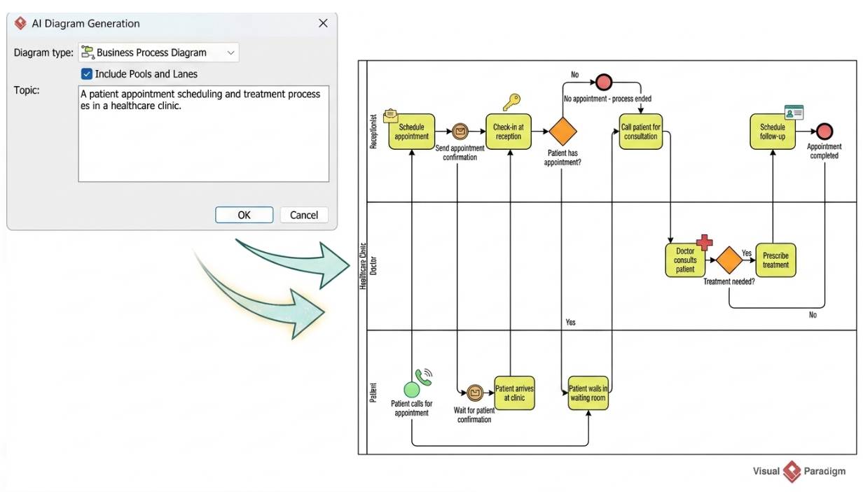
A prompt is more effective when it states the actors, ordered actions, conditions, and outcomes explicitly. For example:
A customer submits an order. Sales checks inventory. If the item is in stock, Warehouse packs it and Shipping delivers it. If it is out of stock, Sales informs the customer and cancels the order. The process ends when the order is delivered or canceled.
For more complex processes, include:
-
Trigger and scope: what starts the process and what is included or excluded.
-
Participants: people, departments, systems, customers, or external providers.
-
Actions: steps in chronological order, using concrete verbs.
-
Conditions: the exact basis for each decision and the possible outcomes.
-
Parallel work: which activities happen at the same time and what must finish before work continues.
-
Exceptions: what happens on timeout, rejection, error, cancellation, or missing information.
-
End states: the possible ways the process completes.
Avoid vague instructions such as “map the order process” without describing what actually happens. Visual Paradigm’s guidance likewise recommends a chronological narrative with explicit actors, actions, conditions, and outcomes; its Desktop instructions describe selecting Tools > AI Diagram Generation, choosing Business Process Diagram, and enabling Include Pools and Lanes where that option is available in the workflow. Interface names and availability can vary by product version or edition.
Refine the generated model
After generation:
-
Check that every task is assigned to the correct participant or lane.
-
Confirm that gateways express the intended logic and that outgoing branches are labeled.
-
Inspect joins, loops, parallel work, and exception handling.
-
Verify that message flows cross participant boundaries and sequence flows stay within the process.
-
Replace guessed or ambiguous steps with facts from process owners.
-
Break complex activities into subprocesses when the overview becomes hard to read.
-
Add annotations or data artifacts only when they clarify the process.
-
Ask participants to walk through realistic cases, including exceptions.
Visual Paradigm describes additional modeling workflows such as subprocess drill-down, procedure documentation, collaboration, and as-is/to-be analysis. Use these to add detail or support review without overcrowding the main process diagram.
5. Example: order fulfillment
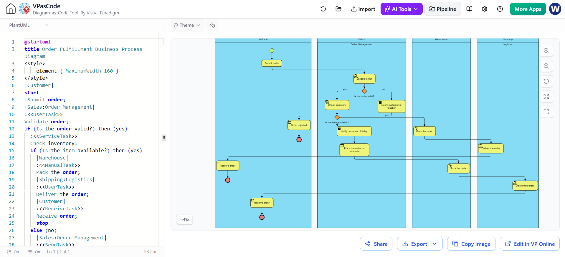
A high-level order process could be modeled as follows:
-
Start event: Customer submits order.
-
Sales task: Validate order.
-
Gateway: Is the order valid?
-
No: Notify customer; end as rejected.
-
Yes: Check inventory.
-
-
Gateway: Is the item available?
-
No: Notify customer and cancel, or place the order on backorder—choose the actual business rule.
-
Yes: Warehouse packs the order.
-
-
Shipping task: Deliver the order.
-
End event: Order fulfilled.
If the customer, company, and shipping provider are modeled as separate pools, use message flows for communication between them. If Sales, Warehouse, and Shipping are roles inside one organization’s process, they can be lanes within that organization’s pool. The correct structure depends on who the participants are and what the diagram is intended to communicate.
6. Quality checklist
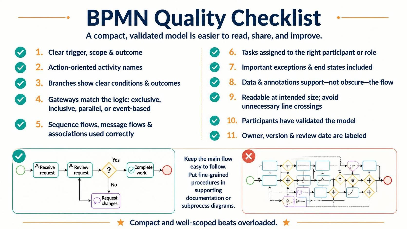
Before sharing or publishing a BPMN diagram, check that:
-
The process has a clear trigger, scope, and outcome.
-
Every activity has a clear action-oriented name.
-
Every branch has understandable conditions and outcomes.
-
Gateways match the logic: exclusive, inclusive, parallel, or event-based.
-
Sequence flows, message flows, and associations are used for their distinct purposes.
-
Each task is assigned to the right participant or role.
-
Important exceptions and end states are represented.
-
Data and annotations support the flow rather than obscure it.
-
The diagram is readable at its intended viewing size and does not have avoidable line crossings.
-
Process participants have validated the model.
-
The diagram is labeled with an owner, version, and review date.
A compact, well-scoped diagram is usually more useful than one page overloaded with every procedural detail. Keep the main flow easy to follow, and place fine-grained procedures in supporting documentation or subprocess diagrams.
Conclusion
BPMN turns complex business work into a shared, visual model that teams can understand, review, and improve. A strong diagram starts with a clear scope and an accurate account of the process, then uses events, activities, gateways, flows, and swimlanes consistently to show what happens, who is responsible, and how different outcomes are handled.
Visual Paradigm’s AI-assisted features can speed up the first draft, but process owners must validate the logic, roles, exceptions, and BPMN notation before relying on it. Treat the model as a living document: review it with stakeholders, keep it readable, and update it as the process changes.

