Designing secure and robust authentication systems requires precision. A single misstep in the logic can lead to security vulnerabilities or poor user experiences. This guide explores how to model complex authentication processes using the UML Interaction Overview Diagram (IOD). We will walk through a comprehensive case study that addresses multi-factor authentication, token management, and session handling without referencing specific vendor tools.
Why Use an Interaction Overview Diagram for Authentication? 🔍
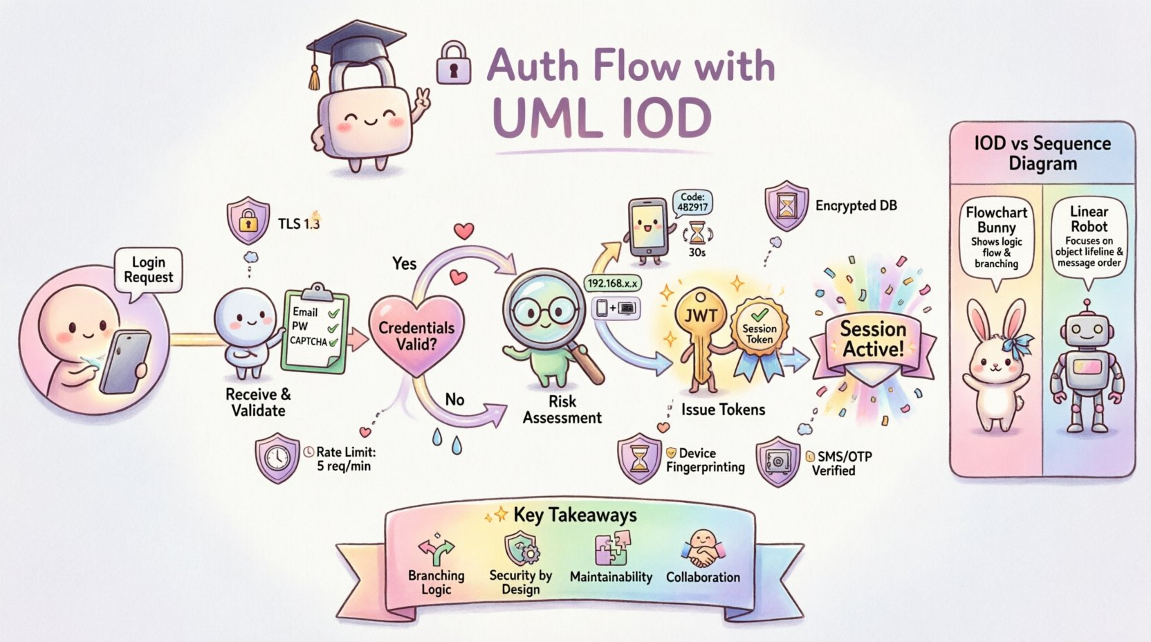
Standard sequence diagrams are excellent for linear flows. However, authentication is rarely linear. It involves branching logic, retries, fallbacks, and state changes. The Interaction Overview Diagram provides a high-level view of control flow, allowing architects to visualize the decision points and sub-activities within a larger system process.
Using IOD for authentication offers several distinct advantages:
- Macro View: It captures the entire lifecycle from request to session termination.
- Branching Logic: It clearly shows where the system decides to proceed based on validation results.
- Reusability: Complex sub-processes (like 2FA verification) can be encapsulated as activity nodes.
- Clarity: It separates the control flow from the detailed message exchange found in sequence diagrams.
Scenario Definition: The Enterprise Login Context 🏢
For this case study, we define a realistic scenario. A user attempts to access a protected resource within a web application. The system must verify identity, validate credentials, check for multi-factor requirements, and issue a session token.
Key Actors Involved:
- User: The individual attempting to access the system via a client device.
- Client Application: The frontend interface handling input and displaying status.
- Authentication Service: The backend logic responsible for credential validation.
- Identity Provider: The external or internal store managing user credentials and profiles.
- Session Manager: The component responsible for issuing and tracking active sessions.
Core Requirements:
- Support for standard username/password verification.
- Trigger for Multi-Factor Authentication (MFA) based on risk profile.
- Secure token issuance (access and refresh tokens).
- Graceful handling of incorrect credentials or expired sessions.
Diagram Structure: Nodes and Control Flow 🔄
The Interaction Overview Diagram consists of specific nodes that represent actions or activities. Each node contains a reference to a sub-diagram (often a sequence diagram) that details the internal message passing.
Primary Nodes in this Flow:
- Initial Node: Marks the entry point where the authentication request is initiated.
- Decision Node: A diamond shape indicating a boolean check (e.g., Is the user valid?).
- Activity Node: Rectangles representing processes like “Validate Credentials” or “Generate Token”.
- Final Node: Marks the successful end of the authentication process.
- Exception Node: Represents error states that branch off the main path.
Step-by-Step Flow Walkthrough 🚀
Let us dissect the authentication lifecycle as it would appear in the Interaction Overview Diagram. This breakdown highlights the decision points and the flow of control between components.
1. Initial Request and Input Validation
The flow begins when the client submits login credentials. The first activity node is labeled Receive Login Request. This node encapsulates the logic for parsing the incoming data payload.
- Action: Parse JSON body for username and password.
- Validation: Check for empty fields or malformed syntax.
- Branch: If invalid, route to an error handler node. If valid, proceed to the authentication service.
2. Credential Verification
The next major node is Verify Credentials. This is a critical security boundary. The interaction diagram for this node would show the authentication service querying the identity provider.
- Process: Hash the provided password and compare it against the stored hash.
- Outcome: The decision node following this activity determines the next step.
- Success Path: The user identity is confirmed. Proceed to risk assessment.
- Failure Path: Log the attempt and return a generic error message to prevent user enumeration.
3. Risk Assessment and MFA Trigger
Not all users require the same level of verification. This stage introduces conditional logic into the flow.
- Activity: Evaluate Risk Profile.
- Logic: Check IP reputation, device familiarity, and location anomalies.
- Decision: Is Multi-Factor Authentication required?
- If Yes: Route to the Initiate MFA activity node. This node triggers a secondary verification step.
- If No: Proceed directly to Issue Tokens.
4. Multi-Factor Authentication (MFA) Handling
If the risk assessment flags the user, the flow branches into the MFA sub-process. This ensures that even if credentials are compromised, access is restricted without the second factor.
- Activity: Send Verification Code.
- Wait State: The system pauses until the user provides the code.
- Validation: Check code validity and expiration.
- Loop: If the code is incorrect, allow retries up to a defined limit. If the limit is reached, terminate the flow.
5. Token Generation and Session Creation
Once verification is complete, the system must establish a trusted session. This is the Issue Tokens activity node.
- Output: Generate Access Token (short-lived) and Refresh Token (long-lived).
- Storage: Persist the token ID in the session store.
- Logging: Record the successful login event for audit trails.
- Final State: Return the tokens to the client application.
Comparing Diagram Types: IOD vs. Sequence Diagram 📊
Understanding when to use an Interaction Overview Diagram versus a Sequence Diagram is vital for documentation quality. The following table outlines the differences.
| Feature | Interaction Overview Diagram | Sequence Diagram |
|---|---|---|
| Focus | Control flow and high-level logic | Message exchange and timing |
| Complexity | Best for branching and loops | Best for linear, detailed interactions |
| Abstraction | High (Nodes represent sub-processes) | Low (Shows specific method calls) |
| Use Case | Architecture planning and risk analysis | Implementation details and debugging |
In this authentication case study, the IOD is the primary document for stakeholders. It answers “What happens?” and “When does it branch?”. The sequence diagrams are nested within the IOD nodes to answer “How does it work?”.
Handling Exceptions and Timeouts ⏱️
A robust system must handle failure gracefully. The Interaction Overview Diagram allows us to map out exception paths clearly, ensuring they are not overlooked during development.
Timeout Scenarios
- MFA Timeout: If the user does not respond to the MFA prompt within 5 minutes, the flow routes to a Session Expired node.
- Service Timeout: If the Identity Provider does not respond within 3 seconds, the flow routes to a Retry or Fail node.
Security Exceptions
- Too Many Attempts: After 5 failed login attempts, the flow triggers a Account Lockout activity.
- Invalid Signature: If a token signature is invalid upon refresh, the flow routes to Force Logout.
Mapping these paths in the IOD ensures that developers understand that error handling is part of the primary design, not an afterthought.
Common Pitfalls in Authentication Modeling 🚫
Even with a solid diagram, implementation errors occur. The table below highlights common modeling mistakes and their real-world consequences.
| Pitfall | Consequence | Mitigation in IOD |
|---|---|---|
| Missing Branches | Uncaught errors lead to crashes | Ensure every decision node has an “Else” path. |
| State Leakage | Sensitive data exposed in logs | Label nodes with data handling requirements (e.g., “Redact Password”). |
| Unclear Loops | Infinite retry loops cause DoS | Explicitly define counter limits in the activity node description. |
| Over-Abstraction | Developers miss critical logic | Link detailed sequence diagrams to complex nodes. |
Maintaining the Diagram Over Time 📈
Authentication requirements evolve. New regulations, updated security standards, and changing user behaviors necessitate updates to the system design. The Interaction Overview Diagram serves as a living document that should be reviewed regularly.
Review Triggers
- Security Audits: After every penetration test, update the diagram to reflect new findings.
- Feature Updates: When adding biometric login or social SSO, add new nodes to the flow.
- Performance Issues: If latency increases, review the token generation node for optimization opportunities.
Version Control
Treat the diagram files with the same version control discipline as code. Each change to the authentication flow should be tagged. This allows teams to trace back which version of the flow supported a specific feature release.
Implementation Guidelines for Developers 👨💻
When developers read the Interaction Overview Diagram, they need clear instructions on how to translate the visual nodes into code. The following guidelines help bridge the gap between design and implementation.
- Stateless Design: Ensure the Authentication Service does not hold session state internally. Rely on the Session Manager node.
- Idempotency: Token generation requests must be idempotent to prevent duplicate session creation.
- Logging Standards: Map the “Log Event” activities in the diagram to specific log levels (INFO, WARN, ERROR).
- Interface Contracts: Define the input and output schemas for each Activity Node before coding begins.
Security Considerations in the Flow 🔒
Security is not a feature; it is a constraint woven into every node. The IOD helps visualize where these constraints apply.
- Data Encryption: The Receive Login Request node must enforce TLS 1.3.
- Token Expiry: The Issue Tokens node must define strict TTL (Time To Live) values.
- Rate Limiting: The Verify Credentials node must integrate with a rate limiter to prevent brute-force attacks.
- Secure Storage: The Store Session activity must use encrypted storage mechanisms.
By explicitly mapping these requirements to nodes, the diagram becomes a checklist for security compliance.
Final Considerations for Architecture Teams 🏗️
Designing an authentication flow is a balancing act between security, performance, and usability. The Interaction Overview Diagram provides the framework to manage this complexity. It allows teams to see the forest and the trees simultaneously.
When adopting this approach, keep the following points in mind:
- Collaboration: Involve security engineers during the diagramming phase, not just after implementation.
- Clarity: Avoid overcrowding the diagram. If a node becomes too complex, decompose it into a sub-diagram.
- Documentation: Ensure every decision node has a clear label explaining the logic criteria.
- Testing: Use the diagram to generate test cases. Every branch should have a corresponding test scenario.
Adopting a structured modeling approach reduces technical debt and prevents security gaps. It transforms authentication from a black box into a transparent, manageable process.
Summary of Key Takeaways 📝
- Visual Clarity: IODs are superior for showing branching logic in authentication compared to linear diagrams.
- Comprehensive Coverage: Include success paths, failure paths, and timeout scenarios in the initial design.
- Security by Design: Map security constraints directly to activity nodes.
- Maintainability: Treat diagrams as living documents that evolve with the system.
- Collaboration: Use diagrams as a communication tool between architects, developers, and security teams.
By following this structured approach, organizations can build authentication systems that are secure, scalable, and easy to maintain. The Interaction Overview Diagram remains a powerful tool in the architect’s toolkit for navigating the complexities of modern identity management.

