Software development often begins with a vague idea or a specific business need. To translate these abstract requirements into a working system, engineers rely on structured methodologies. Object-Oriented Analysis and Design (OOAD) stands as one of the most robust frameworks for this transition. It shifts the focus from procedural logic to the interaction between objects, mirroring real-world entities and their behaviors. This guide provides a structured pathway to move from initial concepts to a concrete class diagram within a single day.
Understanding the Core Philosophy 🧠
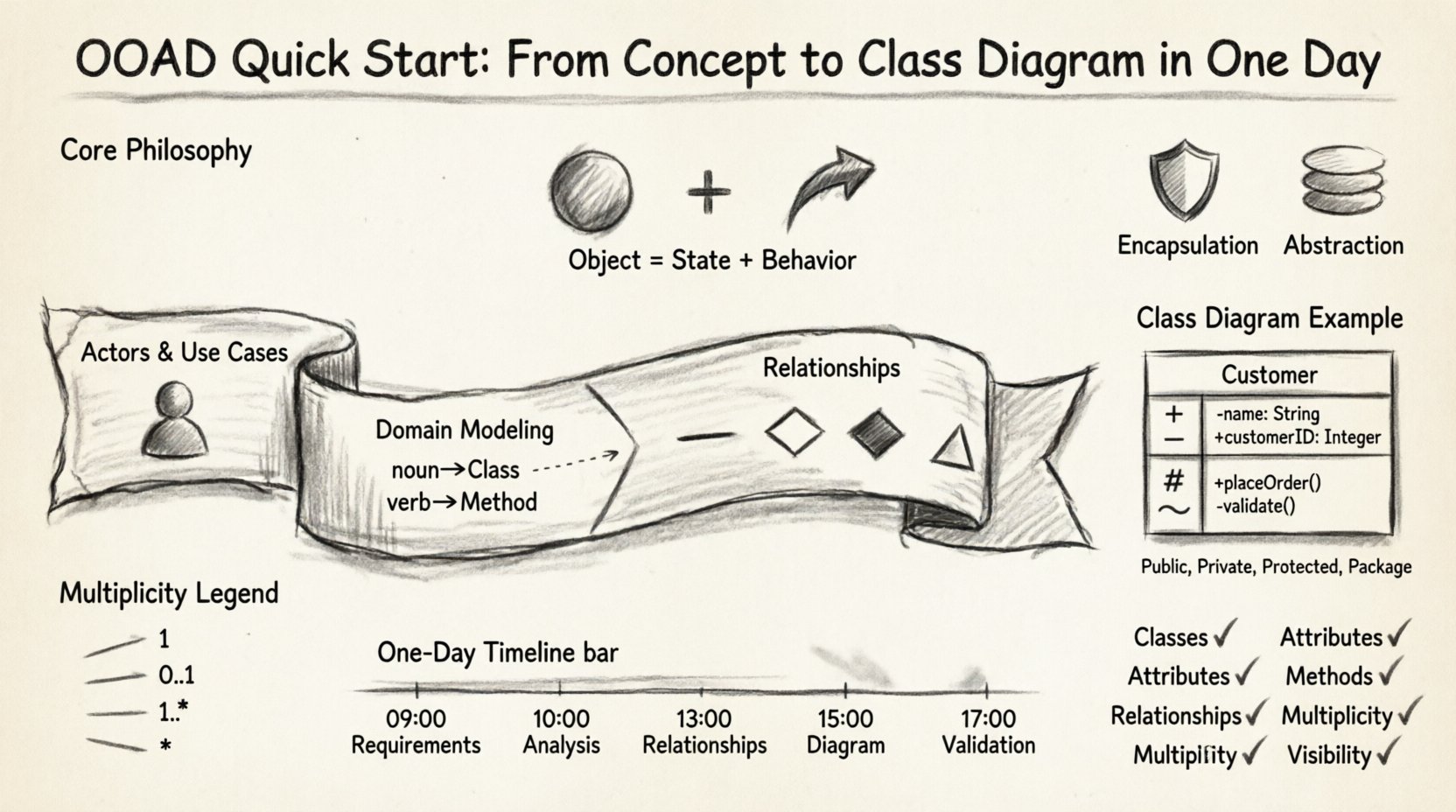
Before diving into the mechanics of diagramming, it is essential to grasp the underlying philosophy of object-oriented thinking. Unlike procedural programming, which organizes code around actions and functions, object-oriented design organizes code around data and the operations that manipulate that data. In OOAD, the “object” is the fundamental building block.
An object consists of two primary components:
- State: The data or attributes that describe the object at any given moment.
- Behavior: The methods or operations that the object can perform.
When you analyze a system using OOAD, you are essentially identifying the nouns (objects) and verbs (behaviors) within the problem domain. This linguistic approach simplifies the abstraction process. Instead of asking “what should the program do?”, you ask “what are the things involved, and how do they interact?”.
This approach offers several advantages:
- Modularity: Components are self-contained and can be developed independently.
- Reusability: Classes can be inherited and reused across different parts of a system.
- Maintainability: Changes in one object do not necessarily impact others, provided interfaces remain stable.
Phase 1: Conceptualization and Requirements 📋
The first day begins with gathering information. You cannot design a solution if you do not understand the problem. This phase focuses on understanding the scope and the actors involved.
Identifying the Actors
An actor is anyone or anything that interacts with the system. Actors can be human users, external systems, or hardware devices. Listing them helps define the boundaries of the system.
- Primary Actors: Users who initiate interactions to achieve a goal (e.g., a Customer, an Administrator).
- Secondary Actors: Systems that support the primary actors but are not the main focus (e.g., a Payment Gateway, an Email Server).
Defining Use Cases
A use case describes a specific interaction between an actor and the system to achieve a result. It answers the question: “What can the actor do?”.
- Example: “Place Order” is a use case for a “Customer”.
- Example: “Process Payment” is a use case for a “Payment Service”.
During this phase, avoid technical details. Focus on functionality. Write down every distinct interaction you can imagine. Do not worry about how the system will achieve these functions yet; just document that they must happen.
Phase 2: Domain Analysis and Modeling 🏗️
Once the requirements are clear, the focus shifts to the domain. This involves identifying the concepts that exist within the business context. This step bridges the gap between business requirements and technical implementation.
Extracting Nouns and Verbs
Review your use case descriptions and highlight the nouns and verbs. These are the seeds of your class diagram.
- Nouns: These typically map to Classes. (e.g., Order, Product, Customer, Invoice).
- Verbs: These typically map to Methods or Associations. (e.g., Create, Delete, Update, Send).
Distinguishing Entities
Not every noun represents a class. Some nouns represent attributes. To distinguish between a Class and an Attribute, ask: “Does this noun have its own identity and state?”.
- Class: “Customer” has a name, address, and history. It exists independently.
- Attribute: “Name” is a property of a Customer. It does not exist on its own.
Phase 3: Designing Relationships 🔗
Objects do not exist in isolation. They relate to one another. Defining these relationships is critical for a functional design. There are four primary types of relationships you must understand.
1. Association
An association represents a structural link between objects. It indicates that objects of one class are connected to objects of another class.
- Example: A Customer owns an Order.
- Direction: Can be unidirectional (Customer knows Order) or bidirectional (Order knows Customer).
2. Aggregation
Aggregation is a specific type of association representing a “whole-part” relationship. The parts can exist independently of the whole.
- Example: A Department has Employees. If the Department is dissolved, the Employees still exist.
- Symbol: Usually depicted as a hollow diamond on the “whole” side.
3. Composition
Composition is a stronger form of aggregation. The parts cannot exist without the whole. If the whole is destroyed, the parts are destroyed.
- Example: A House has Rooms. If the House is demolished, the Rooms cease to exist.
- Symbol: Filled diamond on the “whole” side.
4. Inheritance (Generalization)
Inheritance allows a class to acquire the properties and behaviors of another class. This promotes code reuse and establishes a hierarchy.
- Example: A “SavingsAccount” is a type of “BankAccount”.
- Symbol: Solid line with a hollow triangle pointing to the parent class.
Phase 4: Creating the Class Diagram 📐
The class diagram is the blueprint of your system. It visualizes the classes, their attributes, methods, and relationships. This is the tangible output of your OOAD process.
Class Structure
Each class in the diagram is typically divided into three compartments:
- Name: The identifier for the class (e.g.,
Customer). - Attributes: The data members (e.g.,
customerID: Integer,name: String). - Methods: The behaviors (e.g.,
getBalance(): Float,deposit(amount: Float)).
Visibility Modifiers
Control access to class members using visibility modifiers. This is crucial for encapsulation.
| Symbol | Modifier | Accessibility |
|---|---|---|
+ |
Public | Accessible from anywhere. |
- |
Private | Accessible only within the class. |
# |
Protected | Accessible within the class and its subclasses. |
~ |
Package | Accessible within the same package. |
Cardinality and Multiplicity
Relationships are not just binary; they involve quantities. Multiplicity defines how many instances of one class relate to one instance of another.
- 1: Exactly one.
- 0..1: Zero or one.
- 1..*: One or more.
- *: Zero or more.
For example, a Customer places 1..* Orders. An Order is placed by 0..1 Customer (in some systems, anonymous orders are allowed). Defining these numbers prevents logical errors in the system design.
Phase 5: Refinement and Validation 🛠️
After drawing the initial diagram, review it against the requirements. A diagram is not complete until it is validated. This step ensures the design matches the intended functionality.
Checklist for Validation
- Completeness: Do all use cases have corresponding classes or methods?
- Consistency: Are attribute types consistent across related classes?
- Clarity: Can a developer read the diagram and understand the logic without ambiguity?
- Feasibility: Can the system be implemented with the current technology stack?
Common Design Flaws
Avoid the following common mistakes during this phase:
- God Class: A class that contains too much logic and data. Split this into smaller, focused classes.
- Spaghetti Relationships: Too many associations between classes create tight coupling. Aim for loose coupling.
- Missing Attributes: Forgetting critical data fields that are mentioned in requirements.
- Over-Engineering: Creating complex inheritance hierarchies before they are necessary. Keep it simple.
Deep Dive: Encapsulation and Abstraction 🛡️
While building the class diagram, keep two principles in mind: Encapsulation and Abstraction.
Encapsulation
Encapsulation bundles data and methods together and restricts direct access to some of an object’s components. In your class diagram, this is reflected by marking internal data as private and exposing public methods to interact with it.
- Benefit: Protects the integrity of the object’s state.
- Implementation: Use setters and getters where appropriate, but expose methods that represent business logic rather than simple data access.
Abstraction
Abstraction focuses on hiding complex implementation details and showing only the essential features of the object. This allows different parts of the system to interact without knowing the internal workings.
- Benefit: Reduces complexity and increases modularity.
- Implementation: Define interfaces for classes that require specific behaviors. Ensure the class diagram reflects these contracts.
Step-by-Step Workflow Summary 🔄
To ensure you complete this process in one day, follow this chronological workflow.
- 09:00 – 10:00: Gather requirements and identify actors. (Use Case List)
- 10:00 – 12:00: Analyze the domain. Identify nouns and verbs. (Draft Classes)
- 12:00 – 13:00: Lunch break and mental reset.
- 13:00 – 15:00: Define relationships and cardinality. (Association Mapping)
- 15:00 – 17:00: Draw the Class Diagram. Add attributes and methods. (Final Diagram)
- 17:00 – 18:00: Review and validate against requirements. (Quality Check)
Best Practices for Long-Term Success 📈
While this guide covers the quick start, maintaining a high-quality design requires ongoing discipline. Adhere to these practices as you move into the coding phase.
Single Responsibility Principle
Ensure every class has one reason to change. If a class handles both data storage and business logic, it is too complex. Separate concerns into different classes.
Interface Segregation
Clients should not be forced to depend on interfaces they do not use. Design small, specific interfaces rather than one large, monolithic interface.
Dependency Inversion
Depend on abstractions, not concretions. The class diagram should show high-level modules depending on low-level abstractions (interfaces), not on specific implementation details.
Conclusion on Design Evolution 🌱
Object-Oriented Analysis and Design is not a one-time activity. It is an iterative process. As requirements evolve, your class diagrams must evolve with them. A well-structured diagram today reduces the cost of changes tomorrow. By focusing on clear nouns, robust relationships, and encapsulated behavior, you lay a foundation for scalable software.
Remember, the goal is not to create a perfect diagram immediately, but to create a clear communication tool. This tool bridges the gap between business stakeholders and technical developers. When both parties understand the class diagram, development becomes a matter of translation rather than interpretation.
Final Checklist for Your Diagram ✅
Before signing off on your design, verify the following:
- Classes: Are all necessary classes present?
- Attributes: Are data types defined and correct?
- Methods: Do methods match the verbs in the requirements?
- Relationships: Are associations, aggregations, and compositions correctly labeled?
- Multiplicity: Are the cardinalities (1, 0..1, *) accurate?
- Visibility: Are public, private, and protected members correctly marked?
By following this structured approach, you transform vague concepts into a tangible design ready for implementation. Object-oriented design is a skill honed through practice, but starting with these foundational steps ensures a solid trajectory toward professional software architecture.

