In the landscape of software development, the difference between a fragile application and a robust system often lies in how it is conceived before the first line of code is written. This process is known as Object-Oriented Analysis and Design, or OOAD. It is the architectural blueprinting phase that dictates the structure, behavior, and maintainability of the final product. Understanding these concepts is not merely about following a methodology; it is about thinking in terms of interactions, responsibilities, and relationships.
This guide serves as a foundational resource. We will explore the mechanics of OOAD, breaking down complex theoretical ideas into practical understanding. By the end of this reading, you will have a clear mental model of how to approach building software systems using object-oriented principles.
Understanding the Object-Oriented Paradigm 🧠
Software has evolved from linear scripts to complex systems. The Object-Oriented (OO) paradigm organizes code around “objects” rather than actions and logic. An object represents a distinct entity with state and behavior. This shift changes the developer’s focus from “what does the program do?” to “what objects exist in this domain, and how do they interact?”
OOAD is the structured approach to defining these objects and their interactions. It consists of two primary phases:
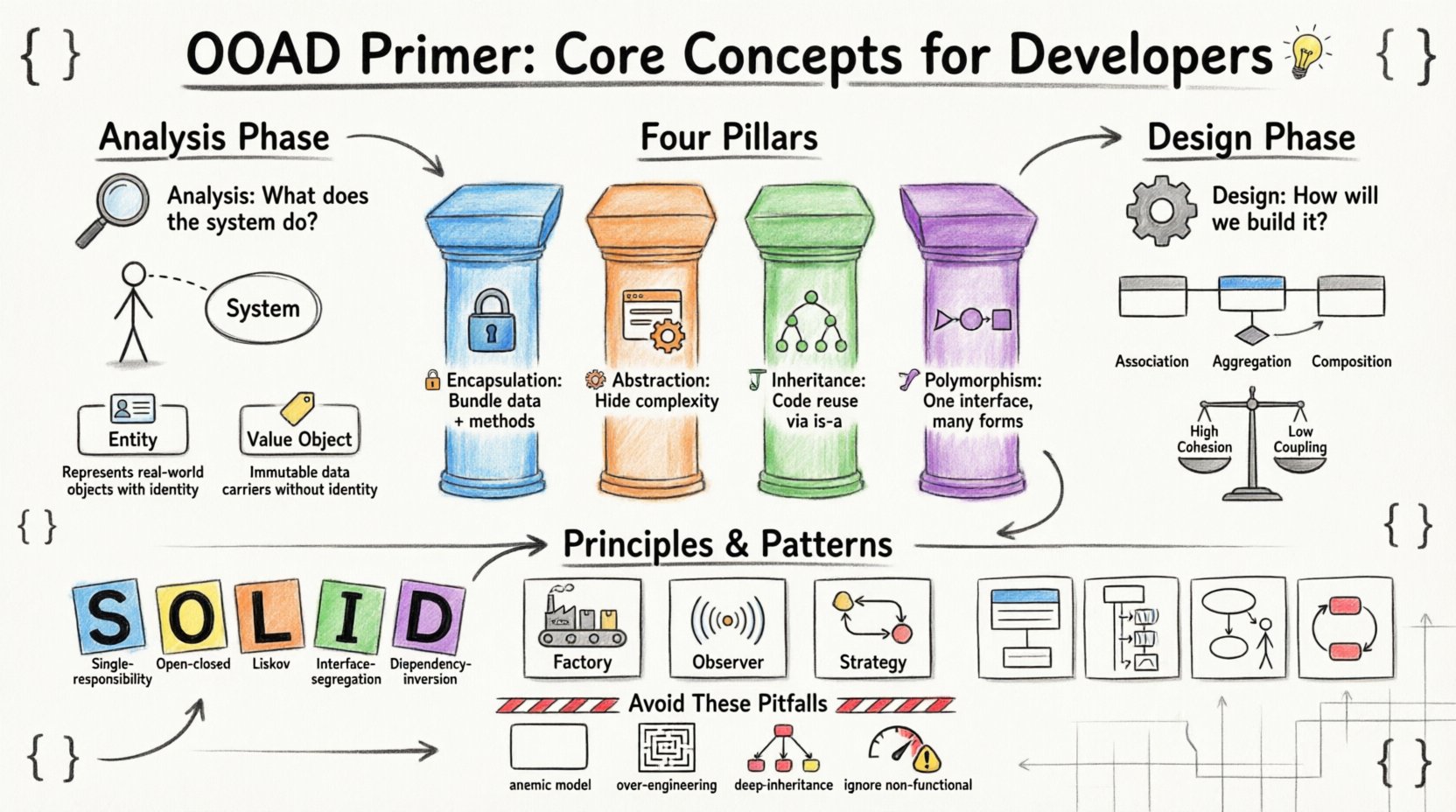
- Analysis: Focuses on understanding the problem domain. It asks “What does the system need to do?” without worrying about implementation details.
- Design: Focuses on the solution. It asks “How will the system be built?” translating requirements into a technical structure.
These phases are not always linear. They often iterate as understanding deepens. Skipping this planning stage usually results in high technical debt, where code becomes difficult to modify over time.
The Four Pillars of Object-Oriented Programming 🏗️
Before diving into analysis and design, one must grasp the underlying pillars that support the paradigm. These principles guide how objects are structured and how they relate to one another. Ignoring these often leads to tight coupling and brittle code.
1. Encapsulation 🔒
Encapsulation is the bundling of data with the methods that operate on that data. It restricts direct access to some of an object’s components, which is a means of preventing unintended interference and misuse of the data.
- Why it matters: It creates a boundary. Other parts of the system interact with the object through a defined interface, not by manipulating internal variables directly.
- Benefit: If the internal implementation changes, external code does not break, provided the interface remains the same.
2. Abstraction 🎭
Abstraction focuses on hiding complex implementation details and showing only the essential features of an object. It allows developers to work with high-level concepts without needing to know the low-level mechanics.
- Why it matters: It reduces cognitive load. You can use a “PaymentProcessor” without knowing how the bank API handles the transaction.
- Benefit: It simplifies the complexity of the system, making it easier to manage large codebases.
3. Inheritance 🧬
Inheritance allows a new class to inherit properties and behaviors from an existing class. This promotes code reuse and establishes a hierarchical relationship between classes.
- Why it matters: It models “is-a” relationships. A
Caris aVehicle. ATruckis aVehicle. - Benefit: Common logic is written once in a parent class and shared across children, reducing redundancy.
4. Polymorphism 🎨
Polymorphism allows objects of different types to be treated as objects of a common super-type. It enables the same interface to be used for different underlying forms.
- Why it matters: It allows flexibility. You can have a list of
ShapescontainingCirclesandSquaresand call adraw()method on all of them without knowing their specific types. - Benefit: It supports open-ended extensibility. New types can be added without modifying existing code that uses the common interface.
The Analysis Phase: Defining the Problem 🔍
The analysis phase is about understanding the requirements. It is where you translate business needs into functional specifications. This phase is critical because if the requirements are flawed, the design will be flawed, regardless of how elegant the code is.
Identifying Use Cases 📋
A use case describes a specific interaction between a user (actor) and the system to achieve a goal. It is a narrative of what the system does, not how it does it.
- Actors: These are the users or external systems that interact with your application. They can be human (e.g., “Admin User”) or non-human (e.g., “Payment Gateway API”).
- Scenarios: A use case can have multiple scenarios, including the happy path (everything goes right) and alternative paths (errors or exceptions occur).
When documenting use cases, clarity is key. Avoid technical jargon. Focus on the user’s intent.
Identifying Domain Objects 🧩
During analysis, you scan the problem domain for nouns. These nouns often become candidate classes or objects. For example, in an e-commerce system, nouns might include Customer, Order, Product, and Invoice.
It is important to distinguish between value objects and entity objects:
| Type | Characteristics | Example |
|---|---|---|
| Entity | Has identity, persists over time, lifecycle independent of other objects. | Order (has an ID, exists across sessions) |
| Value Object | No identity, immutable, defined by its attributes. | Address, Money (defined by street/name or amount/currency) |
Correctly classifying these objects ensures the system models reality accurately. Confusing an entity for a value object can lead to data integrity issues.
The Design Phase: Building the Solution 🛠️
Once the analysis phase defines what the system must do, the design phase determines how to build it. This involves creating a structural model of the objects identified during analysis.
Class Diagrams and Relationships 📊
A class diagram is the most common tool used to visualize the static structure of the system. It shows classes, their attributes, methods, and relationships.
Key relationships to model include:
- Association: A structural relationship where objects are connected. (e.g., A
TeacherteachesStudents). - Aggregation: A weak form of association where the whole can exist without the part. (e.g., A
DepartmenthasMembers; if the department closes, members still exist). - Composition: A strong form of association where the part cannot exist without the whole. (e.g., A
HousehasRooms; if the house is demolished, the rooms are gone). - Inheritance: The “is-a” relationship discussed earlier.
Responsibility-Driven Design 🎯
In design, you assign responsibilities to classes. A responsibility is something a class knows or does. This concept helps in determining where logic should reside.
There are three main types of responsibilities:
- Information Hiding: A class is responsible for keeping its internal state private.
- Calculation: A class performs computations (e.g., calculating tax).
- Creation: A class is responsible for instantiating other objects.
When assigning responsibilities, aim for high cohesion and low coupling.
High Cohesion, Low Coupling ⚖️
This is the golden rule of design. It ensures that your system is maintainable and flexible.
- High Cohesion: A class should have a single, well-defined purpose. If a class does five unrelated things, it is low cohesion. If it only handles user authentication, it is high cohesion.
- Low Coupling: Classes should be independent of each other. If you change Class A, Class B should not break. Dependencies should be minimized.
Design Principles and Patterns 📐
Over time, the community has identified recurring problems and solutions. These are known as design patterns and principles. They provide a vocabulary for discussing design decisions.
The SOLID Principles 📜
These five principles guide the creation of maintainable object-oriented software.
- S – Single Responsibility Principle: A class should have only one reason to change. This aligns with high cohesion.
- O – Open/Closed Principle: Software entities should be open for extension but closed for modification. You add new behavior by adding new classes, not by changing existing code.
- L – Liskov Substitution Principle: Objects of a superclass should be replaceable with objects of its subclasses without breaking the application. This ensures inheritance is used correctly.
- I – Interface Segregation Principle: Clients should not be forced to depend on methods they do not use. Split large interfaces into smaller, more specific ones.
- D – Dependency Inversion Principle: Depend on abstractions, not concretions. High-level modules should not depend on low-level modules. Both should depend on abstractions.
Common Design Patterns 🧩
Patterns are templates for solving common problems. They are not code snippets but conceptual structures.
- Factory Pattern: Provides an interface for creating objects in a superclass, allowing subclasses to alter the type of objects that will be created. Useful when the exact type of object is unknown until runtime.
- Observer Pattern: Defines a subscription mechanism to notify multiple objects about events. Ideal for event-driven systems, like updating UI when data changes.
- Strategy Pattern: Defines a family of algorithms, encapsulates each one, and makes them interchangeable. It allows the algorithm to vary independently from clients that use it.
Visualizing the Architecture 🖼️
While text and tables are useful, visual diagrams are often necessary to communicate complex designs to stakeholders. Unified Modeling Language (UML) is the standard for these diagrams.
Key UML Diagrams
| Diagram Type | Purpose | Focus |
|---|---|---|
| Class Diagram | Static structure | Classes, attributes, relationships |
| Sequence Diagram | Dynamic behavior | Interactions over time between objects |
| Use Case Diagram | Functional requirements | Actors and system goals |
| State Machine Diagram | State transitions | States of an object and triggers for change |
Using these diagrams helps ensure that the team shares a common understanding of the system’s behavior. They serve as documentation that remains accurate as long as the model is updated.
Common Pitfalls to Avoid ⚠️
Even with knowledge of the principles, it is easy to make mistakes during the analysis and design process. Being aware of these common traps can save significant time during development.
1. The Anemic Domain Model 🚫
This occurs when classes contain only getters and setters, with no business logic. This pushes the logic into service classes, creating “transaction scripts” that violate encapsulation. Objects should hold their own logic.
2. Over-Engineering 🏗️
Adding complex design patterns and abstractions before they are needed creates unnecessary complexity. YAGNI (You Aren’t Gonna Need It) is a guiding mantra. Build the simplest solution that works for the current requirements.
3. Deep Inheritance Hierarchies 🌳
Creating classes that are 10 levels deep makes the system rigid. Inheritance should be shallow. Prefer composition (having objects contain other objects) over inheritance when possible. It offers more flexibility.
4. Ignoring Non-Functional Requirements 📉
Analysis often focuses on features (functional requirements). However, performance, security, and scalability (non-functional requirements) must be considered early. A design that works functionally but crashes under load is a failed design.
Iterating and Refining 🔄
OOAD is not a one-time event. It is an iterative process. As you implement the system, you will discover new requirements or flaws in the initial design. This is normal.
- Refactoring: The process of restructuring existing code without changing its external behavior. It allows you to improve the design incrementally.
- Feedback Loops: Regularly review the code against the design. If the code diverges significantly, update the design to reflect reality.
Documentation should be kept lightweight. Over-documented systems become obsolete quickly. Focus on documenting decisions that are non-obvious or critical for future maintenance.
Final Thoughts on Building Robust Systems 🚀
Mastering Object-Oriented Analysis and Design is a journey, not a destination. It requires practice, observation, and a willingness to question assumptions. By focusing on the core concepts of encapsulation, abstraction, and clear responsibilities, you can build systems that are not only functional but also adaptable.
The goal is not to create perfect code on the first try. The goal is to create a foundation that allows for growth. When you understand the “why” behind the design decisions, you can navigate changes with confidence. Whether you are working on a small script or a large-scale enterprise application, these principles provide the stability needed to deliver value consistently.
Keep learning, keep designing, and always prioritize clarity over cleverness.
